- 您现在的位置:买卖IC网 > PDF目录11481 > PIC16F946T-I/PT (Microchip Technology)IC PIC MCU FLASH 8KX14 64TQFP PDF资料下载
参数资料
| 型号: | PIC16F946T-I/PT |
| 厂商: | Microchip Technology |
| 文件页数: | 258/274页 |
| 文件大小: | 0K |
| 描述: | IC PIC MCU FLASH 8KX14 64TQFP |
| 产品培训模块: | Asynchronous Stimulus |
| 标准包装: | 1,200 |
| 系列: | PIC® 16F |
| 核心处理器: | PIC |
| 芯体尺寸: | 8-位 |
| 速度: | 20MHz |
| 连通性: | I²C,SPI,UART/USART |
| 外围设备: | 欠压检测/复位,LCD,POR,PWM,WDT |
| 输入/输出数: | 53 |
| 程序存储器容量: | 14KB(8K x 14) |
| 程序存储器类型: | 闪存 |
| EEPROM 大小: | 256 x 8 |
| RAM 容量: | 336 x 8 |
| 电压 - 电源 (Vcc/Vdd): | 2 V ~ 5.5 V |
| 数据转换器: | A/D 8x10b |
| 振荡器型: | 内部 |
| 工作温度: | -40°C ~ 85°C |
| 封装/外壳: | 64-TQFP |
| 包装: | 带卷 (TR) |
| 配用: | MA160011-ND - DAUGHTER BOARD PICDEM LCD 16F91X |
第1页第2页第3页第4页第5页第6页第7页第8页第9页第10页第11页第12页第13页第14页第15页第16页第17页第18页第19页第20页第21页第22页第23页第24页第25页第26页第27页第28页第29页第30页第31页第32页第33页第34页第35页第36页第37页第38页第39页第40页第41页第42页第43页第44页第45页第46页第47页第48页第49页第50页第51页第52页第53页第54页第55页第56页第57页第58页第59页第60页第61页第62页第63页第64页第65页第66页第67页第68页第69页第70页第71页第72页第73页第74页第75页第76页第77页第78页第79页第80页第81页第82页第83页第84页第85页第86页第87页第88页第89页第90页第91页第92页第93页第94页第95页第96页第97页第98页第99页第100页第101页第102页第103页第104页第105页第106页第107页第108页第109页第110页第111页第112页第113页第114页第115页第116页第117页第118页第119页第120页第121页第122页第123页第124页第125页第126页第127页第128页第129页第130页第131页第132页第133页第134页第135页第136页第137页第138页第139页第140页第141页第142页第143页第144页第145页第146页第147页第148页第149页第150页第151页第152页第153页第154页第155页第156页第157页第158页第159页第160页第161页第162页第163页第164页第165页第166页第167页第168页第169页第170页第171页第172页第173页第174页第175页第176页第177页第178页第179页第180页第181页第182页第183页第184页第185页第186页第187页第188页第189页第190页第191页第192页第193页第194页第195页第196页第197页第198页第199页第200页第201页第202页第203页第204页第205页第206页第207页第208页第209页第210页第211页第212页第213页第214页第215页第216页第217页第218页第219页第220页第221页第222页第223页第224页第225页第226页第227页第228页第229页第230页第231页第232页第233页第234页第235页第236页第237页第238页第239页第240页第241页第242页第243页第244页第245页第246页第247页第248页第249页第250页第251页第252页第253页第254页第255页第256页第257页当前第258页第259页第260页第261页第262页第263页第264页第265页第266页第267页第268页第269页第270页第271页第272页第273页第274页
PIC16F946
DS41265A-page 82
Preliminary
2005 Microchip Technology Inc.
4.7.1
FAIL-SAFE CONDITION CLEARING
The
Fail-Safe condition is cleared after a Reset, the
execution of a SLEEP instruction, or a modification of
the SCS bit. While in Fail-Safe condition, the
PIC16F946 uses the internal oscillator as the system
without exiting the Fail-Safe condition.
The Fail-Safe condition must be cleared before the
OSFIF flag can be cleared.
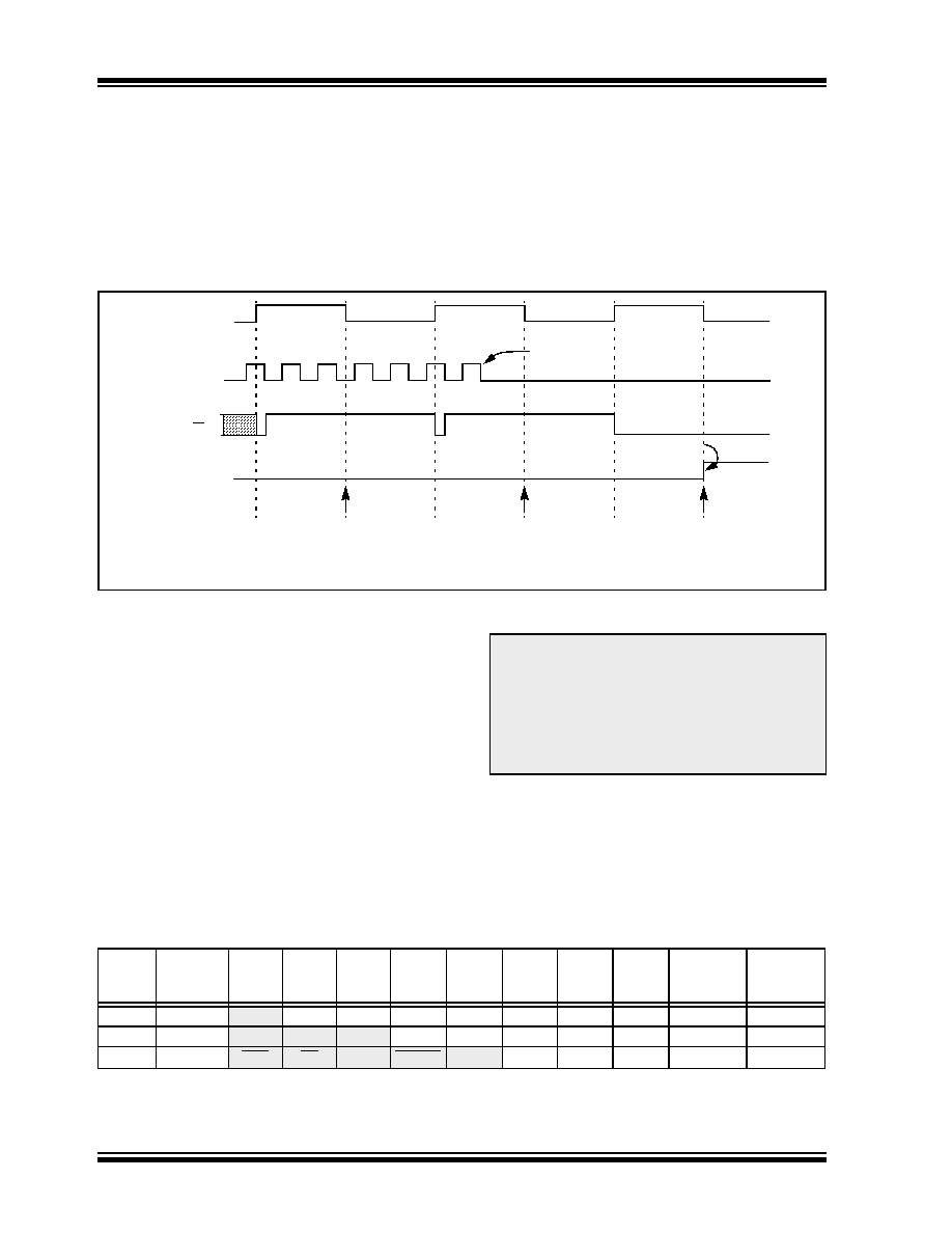
FIGURE 4-9:
FSCM TIMING DIAGRAM
4.7.2
RESET OR WAKE-UP FROM SLEEP
The FSCM is designed to detect oscillator failure at
any point after the device has exited a Reset or Sleep
condition and the Oscillator Start-up Timer (OST) has
expired. If the external clock is EC or RC mode,
monitoring will begin immediately following these
events.
For LP, XT or HS mode the external oscillator may
require a start-up time considerably longer than the
FSCM sample clock time, a false clock failure may be
detected (see Figure 4-9). To prevent this, the internal
oscillator is automatically configured as the system
clock and functions until the external clock is stable
(the OST has timed out). This is identical to
Two-Speed
Start-up
mode.
Once
the
external
oscillator is stable, the LFINTOSC returns to its role as
the FSCM source.
TABLE 4-2:
SUMMARY OF REGISTERS ASSOCIATED WITH CLOCK SOURCES
OSCFIF
CM Output
System
Clock
Output
Sample Clock
Failure
Detected
Oscillator
Failure
Note:
The system clock is normally at a much higher frequency than the sample clock. The relative
frequencies in this example have been chosen for clarity.
(Q)
CM Test
Note:
Due to the wide range of oscillator start-up
times, the Fail-Safe circuit is not active
during oscillator start-up (i.e., after exiting
Reset or Sleep). After an appropriate
amount of time, the user should check the
OSTS bit (OSCCON<3>) to verify the
oscillator
start-up
and
system
clock
switchover has successfully completed.
Addr
Name
Bit 7
Bit 6
Bit 5
Bit 4
Bit 3
Bit 2
Bit 1
Bit 0
Value on:
POR, BOR
Value on
all other
Resets
8Fh
OSCCON
—
IRCF2
IRCF1
IRCF0
OSTS(2)
HTS
LTS
SCS
-110 q000
-110 x000
90h
OSCTUNE
—
TUN4
TUN3
TUN2
TUN1
TUN0
---0 0000
---u uuuu
2007h(1)
CONFIG
CPD
CP
MCLRE PWRTE
WDTE
FOSC2
FOSC1
FOSC0
—
Legend:
x
= unknown, u = unchanged, – = unimplemented locations read as ‘0’. Shaded cells are not used by oscillators.
Note
1:
See Register 16-1 for operation of all Configuration Word bits.
2:
See Register 4-1 for details.
相关PDF资料 |
PDF描述 |
|---|---|
| ADG1434YRUZ | IC SWITCH QUAD SPDT 20TSSOP |
| DSPIC33FJ12MC202T-I/SS | IC DSPIC MCU/DSP 12K 28SSOP |
| PIC18F67J10T-I/PT | IC PIC MCU FLASH 64KX16 64TQFP |
| ADG509FBRNZ | IC MULTIPLEXER DUAL 4X1 16SOIC |
| PIC16C770T-I/SS | IC MCU OTP 2KX14 A/D PWM 20SSOP |
相关代理商/技术参数 |
参数描述 |
|---|---|
| PIC16HV540/JW | 功能描述:8位微控制器 -MCU .75KB 25 RAM 12 I/O RoHS:否 制造商:Silicon Labs 核心:8051 处理器系列:C8051F39x 数据总线宽度:8 bit 最大时钟频率:50 MHz 程序存储器大小:16 KB 数据 RAM 大小:1 KB 片上 ADC:Yes 工作电源电压:1.8 V to 3.6 V 工作温度范围:- 40 C to + 105 C 封装 / 箱体:QFN-20 安装风格:SMD/SMT |
| PIC16HV540-04/P | 功能描述:8位微控制器 -MCU .75KB 25 RAM 12 I/O 4MHz PDIP18 RoHS:否 制造商:Silicon Labs 核心:8051 处理器系列:C8051F39x 数据总线宽度:8 bit 最大时钟频率:50 MHz 程序存储器大小:16 KB 数据 RAM 大小:1 KB 片上 ADC:Yes 工作电源电压:1.8 V to 3.6 V 工作温度范围:- 40 C to + 105 C 封装 / 箱体:QFN-20 安装风格:SMD/SMT |
| PIC16HV540-04/P | 制造商:Microchip Technology Inc 功能描述:IC 8BIT CMOS MCU 16HV540 DIP18 |
| PIC16HV540-04/SO | 功能描述:8位微控制器 -MCU .75KB 25 RAM 12 I/O 4MHz SOIC18 RoHS:否 制造商:Silicon Labs 核心:8051 处理器系列:C8051F39x 数据总线宽度:8 bit 最大时钟频率:50 MHz 程序存储器大小:16 KB 数据 RAM 大小:1 KB 片上 ADC:Yes 工作电源电压:1.8 V to 3.6 V 工作温度范围:- 40 C to + 105 C 封装 / 箱体:QFN-20 安装风格:SMD/SMT |
| PIC16HV540-04/SS | 功能描述:8位微控制器 -MCU .75KB 25 RAM 12 I/O 4MHz SSOP20 RoHS:否 制造商:Silicon Labs 核心:8051 处理器系列:C8051F39x 数据总线宽度:8 bit 最大时钟频率:50 MHz 程序存储器大小:16 KB 数据 RAM 大小:1 KB 片上 ADC:Yes 工作电源电压:1.8 V to 3.6 V 工作温度范围:- 40 C to + 105 C 封装 / 箱体:QFN-20 安装风格:SMD/SMT |
发布紧急采购,3分钟左右您将得到回复。