- 您现在的位置:买卖IC网 > PDF目录3885 > PIC17C756AT-16E/L (Microchip Technology)IC MCU CMOS 16MHZ 16K EPRM68PLCC PDF资料下载
参数资料
| 型号: | PIC17C756AT-16E/L |
| 厂商: | Microchip Technology |
| 文件页数: | 78/159页 |
| 文件大小: | 0K |
| 描述: | IC MCU CMOS 16MHZ 16K EPRM68PLCC |
| 标准包装: | 300 |
| 系列: | PIC® 17C |
| 核心处理器: | PIC |
| 芯体尺寸: | 8-位 |
| 速度: | 16MHz |
| 连通性: | I²C,SPI,UART/USART |
| 外围设备: | 欠压检测/复位,POR,PWM,WDT |
| 输入/输出数: | 50 |
| 程序存储器容量: | 32KB(16K x 16) |
| 程序存储器类型: | OTP |
| RAM 容量: | 902 x 8 |
| 电压 - 电源 (Vcc/Vdd): | 4.5 V ~ 5.5 V |
| 数据转换器: | A/D 12x10b |
| 振荡器型: | 外部 |
| 工作温度: | -40°C ~ 125°C |
| 封装/外壳: | 68-LCC(J 形引线) |
| 包装: | 带卷 (TR) |
| 配用: | AC164308-ND - MODULE SKT FOR PM3 68PLCC DVA17XL681-ND - DEVICE ADAPTER FOR PIC17C752 DM173001-ND - KIT DEVELOPMENT PICDEM17 AC174007-ND - MODULE SKT PROMATEII 68PLCC AC164024-ND - ADAPTER PICSTART PLUS 68PLCC |
第1页第2页第3页第4页第5页第6页第7页第8页第9页第10页第11页第12页第13页第14页第15页第16页第17页第18页第19页第20页第21页第22页第23页第24页第25页第26页第27页第28页第29页第30页第31页第32页第33页第34页第35页第36页第37页第38页第39页第40页第41页第42页第43页第44页第45页第46页第47页第48页第49页第50页第51页第52页第53页第54页第55页第56页第57页第58页第59页第60页第61页第62页第63页第64页第65页第66页第67页第68页第69页第70页第71页第72页第73页第74页第75页第76页第77页当前第78页第79页第80页第81页第82页第83页第84页第85页第86页第87页第88页第89页第90页第91页第92页第93页第94页第95页第96页第97页第98页第99页第100页第101页第102页第103页第104页第105页第106页第107页第108页第109页第110页第111页第112页第113页第114页第115页第116页第117页第118页第119页第120页第121页第122页第123页第124页第125页第126页第127页第128页第129页第130页第131页第132页第133页第134页第135页第136页第137页第138页第139页第140页第141页第142页第143页第144页第145页第146页第147页第148页第149页第150页第151页第152页第153页第154页第155页第156页第157页第158页第159页
PIC17C7XX
DS30289B-page 24
2000 Microchip Technology Inc.
5.1
Power-on Reset (POR), Power-up
Timer (PWRT), Oscillator Start-up
Timer (OST) and Brown-out Reset
(BOR)
5.1.1
POWER-ON RESET (POR)
The Power-on Reset circuit holds the device in RESET
until VDD is above the trip point (in the range of 1.4V -
2.3V). The devices produce an internal RESET for both
rising and falling VDD. To take advantage of the POR,
just tie the MCLR/VPP pin directly (or through a resistor)
to VDD. This will eliminate external RC components
usually needed to create Power-on Reset. A minimum
rise time for VDD is required. See Electrical Specifica-
tions for details.
Figure 5-2 and Figure 5-3 show two possible POR
circuits.
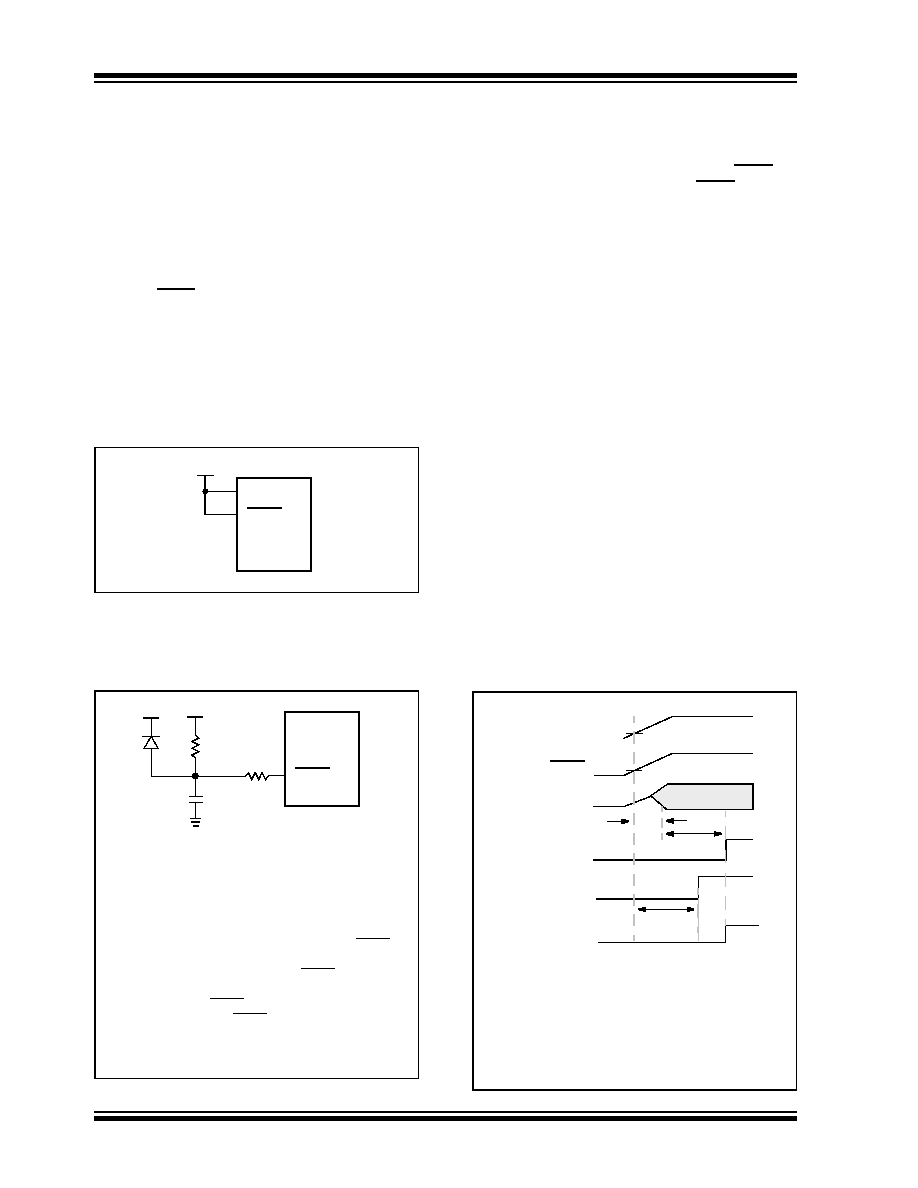
FIGURE 5-2:
USING ON-CHIP POR
FIGURE 5-3:
EXTERNAL POWER-ON
RESET CIRCUIT (FOR
SLOW VDD POWER-UP)
5.1.2
POWER-UP TIMER (PWRT)
The Power-up Timer provides a fixed 96 ms time-out
(nominal) on power-up. This occurs from the rising
edge of the internal POR signal if VDD and MCLR are
tied, or after the first rising edge of MCLR (detected
high). The Power-up Timer operates on an internal RC
oscillator. The chip is kept in RESET as long as the
PWRT is active. In most cases, the PWRT delay allows
VDD to rise to an acceptable level.
The power-up time delay will vary from chip to chip and
with VDD and temperature. See DC parameters for
details.
5.1.3
OSCILLATOR START-UP TIMER
(OST)
The Oscillator Start-up Timer (OST) provides a 1024
oscillator cycle (1024TOSC) delay whenever the PWRT
is invoked, or a wake-up from SLEEP event occurs in XT
or LF mode. The PWRT and OST operate in parallel.
The OST counts the oscillator pulses on the OSC1/
CLKIN pin. The counter only starts incrementing after
the amplitude of the signal reaches the oscillator input
thresholds. This delay allows the crystal oscillator or
resonator to stabilize before the device exits RESET.
The length of the time-out is a function of the crystal/
resonator frequency.
Figure 5-4 shows the operation of the OST circuit. In
this figure, the oscillator is of such a low frequency that
although enabled simultaneously, the OST does not
time-out until after the Power-up Timer time-out.
FIGURE 5-4:
OSCILLATOR START-UP
TIME(LOWFREQUENCY)
VDD
MCLR
PIC17CXXX
VDD
Note
1:
An external Power-on Reset circuit is
required only if VDD power-up time is too
slow. The diode D helps discharge the capac-
itor quickly when VDD powers down.
2: R < 40 k
is recommended to ensure that the
voltage drop across R does not exceed 0.2V
(max. leakage current spec. on the MCLR/
VPP pin is 5
A). A larger voltage drop will
degrade VIH level on the MCLR/VPP pin.
3: R1 = 100
to 1 k will limit any current flow-
ing into MCLR from external capacitor C in
the event of MCLR/VPP pin breakdown due to
Electrostatic Discharge (ESD) or Electrical
Overstress (EOS).
C
R1
R
D
VDD
MCLR
PIC17CXXX
VDD
MCLR
OSC2
OST TIME_OUT
PWRT TIME_OUT
INTERNAL RESET
TOSC1
TOST
TPWRT
POR or BOR Trip Point
This figure shows in greater detail the timings involved
with the oscillator start-up timer. In this example, the low
frequency crystal start-up time is larger than power-up
time (TPWRT).
TOSC1 = time for the crystal oscillator to react to an oscil-
lation level detectable by the Oscillator Start-up Timer
(OST).
TOST = 1024TOSC.
相关PDF资料 |
PDF描述 |
|---|---|
| 1-84983-1 | CONN FFC 11POS 1.00MM R/A PCB |
| PIC17C756A-33E/PT | IC MCU CMOS 33MHZ 16K EPRM64TQFP |
| 1-84983-0 | CONN FFC 10POS 1.00MM R/A PCB |
| PIC17C756A-16E/PT | IC MCU CMOS 16MHZ 16K EPRM64TQFP |
| PIC17C756A-16E/L | IC MCU CMOS 16MHZ 16K EPRM68PLCC |
相关代理商/技术参数 |
参数描述 |
|---|---|
| PIC17C756AT-16I/L | 功能描述:8位微控制器 -MCU 32KB 902 RAM 50 I/O RoHS:否 制造商:Silicon Labs 核心:8051 处理器系列:C8051F39x 数据总线宽度:8 bit 最大时钟频率:50 MHz 程序存储器大小:16 KB 数据 RAM 大小:1 KB 片上 ADC:Yes 工作电源电压:1.8 V to 3.6 V 工作温度范围:- 40 C to + 105 C 封装 / 箱体:QFN-20 安装风格:SMD/SMT |
| PIC17C756AT-16I/PT | 功能描述:8位微控制器 -MCU 32KB 902 RAM 50 I/O RoHS:否 制造商:Silicon Labs 核心:8051 处理器系列:C8051F39x 数据总线宽度:8 bit 最大时钟频率:50 MHz 程序存储器大小:16 KB 数据 RAM 大小:1 KB 片上 ADC:Yes 工作电源电压:1.8 V to 3.6 V 工作温度范围:- 40 C to + 105 C 封装 / 箱体:QFN-20 安装风格:SMD/SMT |
| PIC17C756AT-33/L | 功能描述:8位微控制器 -MCU 32KB 902 RAM 50 I/O RoHS:否 制造商:Silicon Labs 核心:8051 处理器系列:C8051F39x 数据总线宽度:8 bit 最大时钟频率:50 MHz 程序存储器大小:16 KB 数据 RAM 大小:1 KB 片上 ADC:Yes 工作电源电压:1.8 V to 3.6 V 工作温度范围:- 40 C to + 105 C 封装 / 箱体:QFN-20 安装风格:SMD/SMT |
| PIC17C756AT-33/PT | 功能描述:8位微控制器 -MCU 32KB 902 RAM 50 I/O RoHS:否 制造商:Silicon Labs 核心:8051 处理器系列:C8051F39x 数据总线宽度:8 bit 最大时钟频率:50 MHz 程序存储器大小:16 KB 数据 RAM 大小:1 KB 片上 ADC:Yes 工作电源电压:1.8 V to 3.6 V 工作温度范围:- 40 C to + 105 C 封装 / 箱体:QFN-20 安装风格:SMD/SMT |
| PIC17C756AT-33E/L | 功能描述:8位微控制器 -MCU 32KB 902 RAM 50 I/O RoHS:否 制造商:Silicon Labs 核心:8051 处理器系列:C8051F39x 数据总线宽度:8 bit 最大时钟频率:50 MHz 程序存储器大小:16 KB 数据 RAM 大小:1 KB 片上 ADC:Yes 工作电源电压:1.8 V to 3.6 V 工作温度范围:- 40 C to + 105 C 封装 / 箱体:QFN-20 安装风格:SMD/SMT |
发布紧急采购,3分钟左右您将得到回复。