- 您现在的位置:买卖IC网 > PDF目录11313 > PIC18LF4585T-I/PT (Microchip Technology)IC MCU FLASH 24KX16 44TQFP PDF资料下载
参数资料
| 型号: | PIC18LF4585T-I/PT |
| 厂商: | Microchip Technology |
| 文件页数: | 72/322页 |
| 文件大小: | 0K |
| 描述: | IC MCU FLASH 24KX16 44TQFP |
| 产品培训模块: | Asynchronous Stimulus |
| 标准包装: | 1,200 |
| 系列: | PIC® 18F |
| 核心处理器: | PIC |
| 芯体尺寸: | 8-位 |
| 速度: | 40MHz |
| 连通性: | CAN,I²C,SPI,UART/USART |
| 外围设备: | 欠压检测/复位,HLVD,POR,PWM,WDT |
| 输入/输出数: | 36 |
| 程序存储器容量: | 48KB(24K x 16) |
| 程序存储器类型: | 闪存 |
| EEPROM 大小: | 1K x 8 |
| RAM 容量: | 3.25K x 8 |
| 电压 - 电源 (Vcc/Vdd): | 2 V ~ 5.5 V |
| 数据转换器: | A/D 11x10b |
| 振荡器型: | 内部 |
| 工作温度: | -40°C ~ 85°C |
| 封装/外壳: | 44-TQFP |
| 包装: | 带卷 (TR) |
第1页第2页第3页第4页第5页第6页第7页第8页第9页第10页第11页第12页第13页第14页第15页第16页第17页第18页第19页第20页第21页第22页第23页第24页第25页第26页第27页第28页第29页第30页第31页第32页第33页第34页第35页第36页第37页第38页第39页第40页第41页第42页第43页第44页第45页第46页第47页第48页第49页第50页第51页第52页第53页第54页第55页第56页第57页第58页第59页第60页第61页第62页第63页第64页第65页第66页第67页第68页第69页第70页第71页当前第72页第73页第74页第75页第76页第77页第78页第79页第80页第81页第82页第83页第84页第85页第86页第87页第88页第89页第90页第91页第92页第93页第94页第95页第96页第97页第98页第99页第100页第101页第102页第103页第104页第105页第106页第107页第108页第109页第110页第111页第112页第113页第114页第115页第116页第117页第118页第119页第120页第121页第122页第123页第124页第125页第126页第127页第128页第129页第130页第131页第132页第133页第134页第135页第136页第137页第138页第139页第140页第141页第142页第143页第144页第145页第146页第147页第148页第149页第150页第151页第152页第153页第154页第155页第156页第157页第158页第159页第160页第161页第162页第163页第164页第165页第166页第167页第168页第169页第170页第171页第172页第173页第174页第175页第176页第177页第178页第179页第180页第181页第182页第183页第184页第185页第186页第187页第188页第189页第190页第191页第192页第193页第194页第195页第196页第197页第198页第199页第200页第201页第202页第203页第204页第205页第206页第207页第208页第209页第210页第211页第212页第213页第214页第215页第216页第217页第218页第219页第220页第221页第222页第223页第224页第225页第226页第227页第228页第229页第230页第231页第232页第233页第234页第235页第236页第237页第238页第239页第240页第241页第242页第243页第244页第245页第246页第247页第248页第249页第250页第251页第252页第253页第254页第255页第256页第257页第258页第259页第260页第261页第262页第263页第264页第265页第266页第267页第268页第269页第270页第271页第272页第273页第274页第275页第276页第277页第278页第279页第280页第281页第282页第283页第284页第285页第286页第287页第288页第289页第290页第291页第292页第293页第294页第295页第296页第297页第298页第299页第300页第301页第302页第303页第304页第305页第306页第307页第308页第309页第310页第311页第312页第313页第314页第315页第316页第317页第318页第319页第320页第321页第322页
2007 Microchip Technology Inc.
Preliminary
DS39625C-page 161
PIC18F2585/2680/4585/4680
14.2
Timer3 16-Bit Read/Write Mode
Timer3 can be configured for 16-bit reads and writes
(see
When
the
RD16
control
bit
(T3CON<7>) is set, the address for TMR3H is mapped
to a buffer register for the high byte of Timer3. A read
from TMR3L will load the contents of the high byte of
Timer3 into the Timer3 High Byte Buffer register. This
provides the user with the ability to accurately read all
16 bits of Timer1 without having to determine whether
a read of the high byte, followed by a read of the low
byte, has become invalid due to a rollover between
reads.
A write to the high byte of Timer3 must also take place
through the TMR3H Buffer register. The Timer3 high
byte is updated with the contents of TMR3H when a
write occurs to TMR3L. This allows a user to write all
16 bits to both the high and low bytes of Timer3 at once.
The high byte of Timer3 is not directly readable or
writable in this mode. All reads and writes must take
place through the Timer3 High Byte Buffer register.
Writes to TMR3H do not clear the Timer3 prescaler.
The prescaler is only cleared on writes to TMR3L.
14.3
Using the Timer1 Oscillator as the
Timer3 Clock Source
The Timer1 internal oscillator may be used as the clock
source for Timer3. The Timer1 oscillator is enabled by
setting the T1OSCEN (T1CON<3>) bit. To use it as the
Timer3 clock source, the TMR3CS bit must also be set.
As previously noted, this also configures Timer3 to
increment on every rising edge of the oscillator source.
The Timer1 oscillator is described in Section 12.0
14.4
Timer3 Interrupt
The TMR3 register pair (TMR3H:TMR3L) increments
from 0000h to FFFFh and overflows to 0000h. The
Timer3 interrupt, if enabled, is generated on overflow
and is latched in the interrupt flag bit, TMR3IF
(PIR2<1>). This interrupt can be enabled or disabled
by setting or clearing the Timer3 Interrupt Enable bit,
TMR3IE (PIE2<1>).
14.5
Resetting Timer3 Using the
ECCP1 Special Event Trigger
If the ECCP1 module is configured to generate a
special event
trigger
in
Compare
mode
(ECCP1M3:ECCP1M0 = 1011), this signal will reset
Timer3. It will also start an A/D conversion if the A/D
module is enabled (see Section 15.3.4 “Special
Event Trigger” for more information.).
The module must be configured as either a timer or
synchronous counter to take advantage of this feature.
When used this way, the ECCPR1H:ECCPR1L register
pair effectively becomes a period register for Timer3.
If Timer3 is running in Asynchronous Counter mode,
the Reset operation may not work.
In the event that a write to Timer3 coincides with a
special event trigger from a CCP1 module, the write will
take precedence.
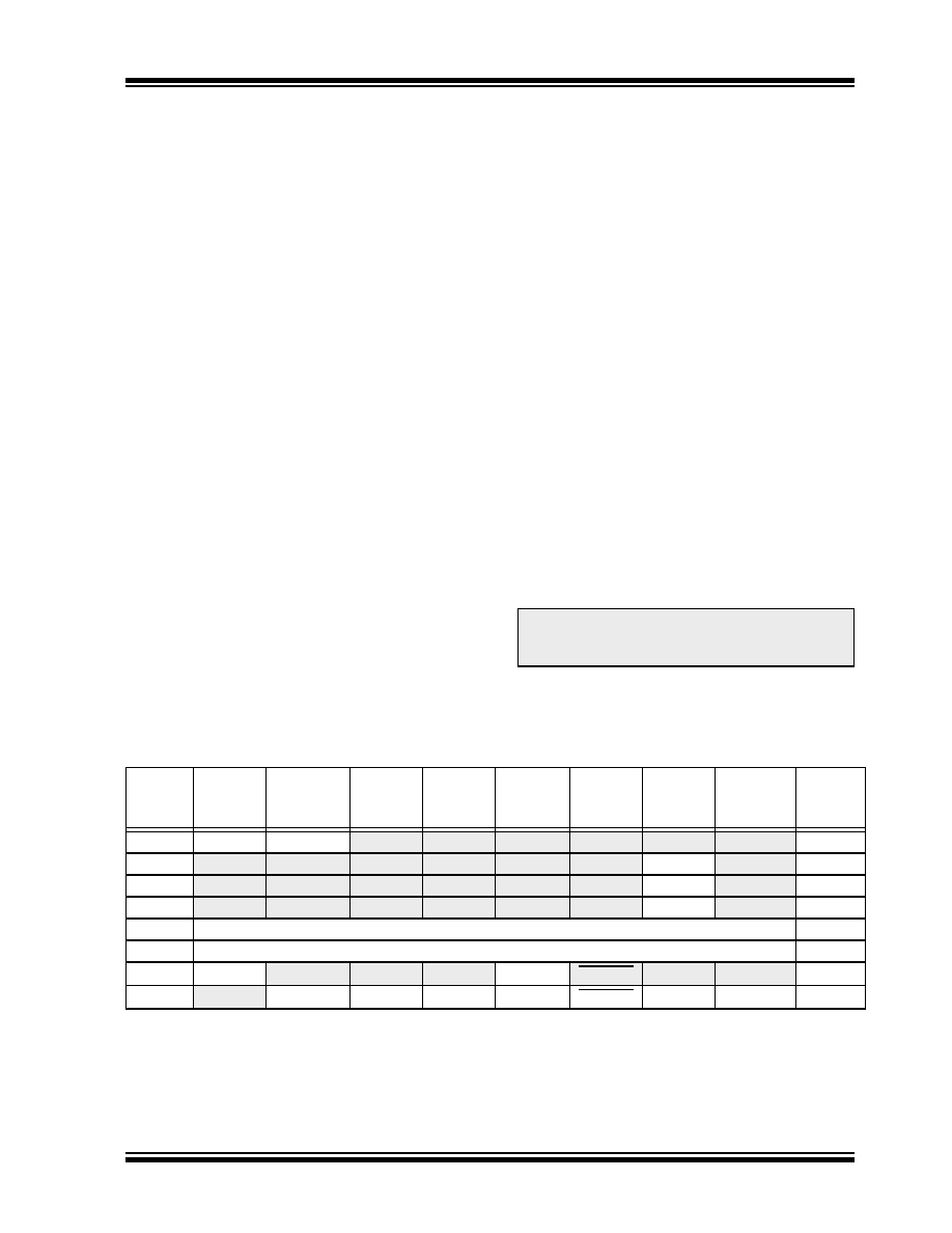
TABLE 14-1:
REGISTERS ASSOCIATED WITH TIMER3 AS A TIMER/COUNTER
Note:
The special event triggers from the
ECCP1 module will not set the TMR3IF
interrupt flag bit (PIR1<0>).
Name
Bit 7
Bit 6
Bit 5
Bit 4
Bit 3
Bit 2
Bit 1
Bit 0
Reset
Values
on page
INTCON
GIE/GIEH
PEIE/GIEL
TMR0IE
INT0IE
RBIE
TMR0IF
INT0IF
RBIF
PIR2
OSCFIF
CMIF(2)
—
EEIF
BCLIF
HLVDIF
TMR3IF
ECCP1IF(2)
PIE2
OSCFIE
CMIE(2)
—
EEIE
BCLIE
HLVDIE
TMR3IE
ECCP1IE(2)
IPR2
OSCFIP
CMIP(2)
—
EEIP
BCLIP
HLVDIP
TMR3IP
ECCP1IP(2)
TMR3L
Timer3 Register, Low Byte
TMR3H
Timer3 Register, High Byte
T1CON
RD16
T1RUN
T1CKPS1 T1CKPS0 T1OSCEN
T1SYNC
TMR1CS
TMR1ON
T3CON
RD16
T3ECCP1(1) T3CKPS1 T3CKPS0 T3CCP1(1) T3SYNC
TMR3CS
TMR3ON
Legend: — = unimplemented, read as ‘0’. Shaded cells are not used by the Timer3 module.
Note 1:
These bits are available in PIC18F4X8X devices only.
2:
These bits are available in PIC18F4X8X devices and reserved in PIC18F2X8X devices.
相关PDF资料 |
PDF描述 |
|---|---|
| RPE5C1H5R0C2P1B03B | CAP CER 5PF 50V RADIAL |
| VE-25V-IX-F1 | CONVERTER MOD DC/DC 5.8V 75W |
| VE-25T-IX-F4 | CONVERTER MOD DC/DC 6.5V 75W |
| RPE5C1H391J2M1A03A | CAP CER 390PF 50V 5% RADIAL |
| RPE5C1H331J2S1A03A | CAP CER 330PF 50V 5% RADIAL |
相关代理商/技术参数 |
参数描述 |
|---|---|
| PIC18LF458-I/L | 功能描述:8位微控制器 -MCU 32KB 1536 RAM 34I/O RoHS:否 制造商:Silicon Labs 核心:8051 处理器系列:C8051F39x 数据总线宽度:8 bit 最大时钟频率:50 MHz 程序存储器大小:16 KB 数据 RAM 大小:1 KB 片上 ADC:Yes 工作电源电压:1.8 V to 3.6 V 工作温度范围:- 40 C to + 105 C 封装 / 箱体:QFN-20 安装风格:SMD/SMT |
| PIC18LF458-I/L | 制造商:Microchip Technology Inc 功能描述:IC 8BIT FLASH MCU 18LF458 PLCC44 |
| PIC18LF458-I/P | 功能描述:8位微控制器 -MCU 32KB 1536 RAM 34I/O RoHS:否 制造商:Silicon Labs 核心:8051 处理器系列:C8051F39x 数据总线宽度:8 bit 最大时钟频率:50 MHz 程序存储器大小:16 KB 数据 RAM 大小:1 KB 片上 ADC:Yes 工作电源电压:1.8 V to 3.6 V 工作温度范围:- 40 C to + 105 C 封装 / 箱体:QFN-20 安装风格:SMD/SMT |
| PIC18LF458-I/P | 制造商:Microchip Technology Inc 功能描述:IC 8BIT FLASH MCU 18LF458 DIP40 |
| PIC18LF458-I/PT | 功能描述:8位微控制器 -MCU 32KB 1536 RAM 34I/O RoHS:否 制造商:Silicon Labs 核心:8051 处理器系列:C8051F39x 数据总线宽度:8 bit 最大时钟频率:50 MHz 程序存储器大小:16 KB 数据 RAM 大小:1 KB 片上 ADC:Yes 工作电源电压:1.8 V to 3.6 V 工作温度范围:- 40 C to + 105 C 封装 / 箱体:QFN-20 安装风格:SMD/SMT |
发布紧急采购,3分钟左右您将得到回复。