- 您现在的位置:买卖IC网 > PDF目录3844 > PIC18LF47J13-I/ML (Microchip Technology)IC PIC MCU 128KB FLASH 44QFN PDF资料下载
参数资料
| 型号: | PIC18LF47J13-I/ML |
| 厂商: | Microchip Technology |
| 文件页数: | 39/71页 |
| 文件大小: | 0K |
| 描述: | IC PIC MCU 128KB FLASH 44QFN |
| 产品培训模块: | 8-bit PIC® Microcontroller Portfolio |
| 标准包装: | 45 |
| 系列: | PIC® XLP™ 18F |
| 核心处理器: | PIC |
| 芯体尺寸: | 8-位 |
| 速度: | 48MHz |
| 连通性: | I²C,LIN,SPI,UART/USART |
| 外围设备: | 欠压检测/复位,POR,PWM,WDT |
| 输入/输出数: | 34 |
| 程序存储器容量: | 128KB(64K x 16) |
| 程序存储器类型: | 闪存 |
| RAM 容量: | 3.8K x 8 |
| 电压 - 电源 (Vcc/Vdd): | 2 V ~ 2.75 V |
| 数据转换器: | A/D 13x10b/12b |
| 振荡器型: | 内部 |
| 工作温度: | -40°C ~ 85°C |
| 封装/外壳: | 44-VQFN 裸露焊盘 |
| 包装: | 管件 |
第1页第2页第3页第4页第5页第6页第7页第8页第9页第10页第11页第12页第13页第14页第15页第16页第17页第18页第19页第20页第21页第22页第23页第24页第25页第26页第27页第28页第29页第30页第31页第32页第33页第34页第35页第36页第37页第38页当前第39页第40页第41页第42页第43页第44页第45页第46页第47页第48页第49页第50页第51页第52页第53页第54页第55页第56页第57页第58页第59页第60页第61页第62页第63页第64页第65页第66页第67页第68页第69页第70页第71页
PIC18(L)F2X/4XK22
DS41412E-page 44
2010-2012 Microchip Technology Inc.
2.13
Fail-Safe Clock Monitor
The Fail-Safe Clock Monitor (FSCM) allows the device
to continue operating should the external oscillator fail.
The FSCM can detect oscillator failure any time after
the Oscillator Start-up Timer (OST) has expired. The
FSCM is enabled by setting the FCMEN bit in the
CONFIG1H Configuration register. The FSCM is
applicable to all external oscillator modes (LP, XT, HS,
EC, RC and RCIO).
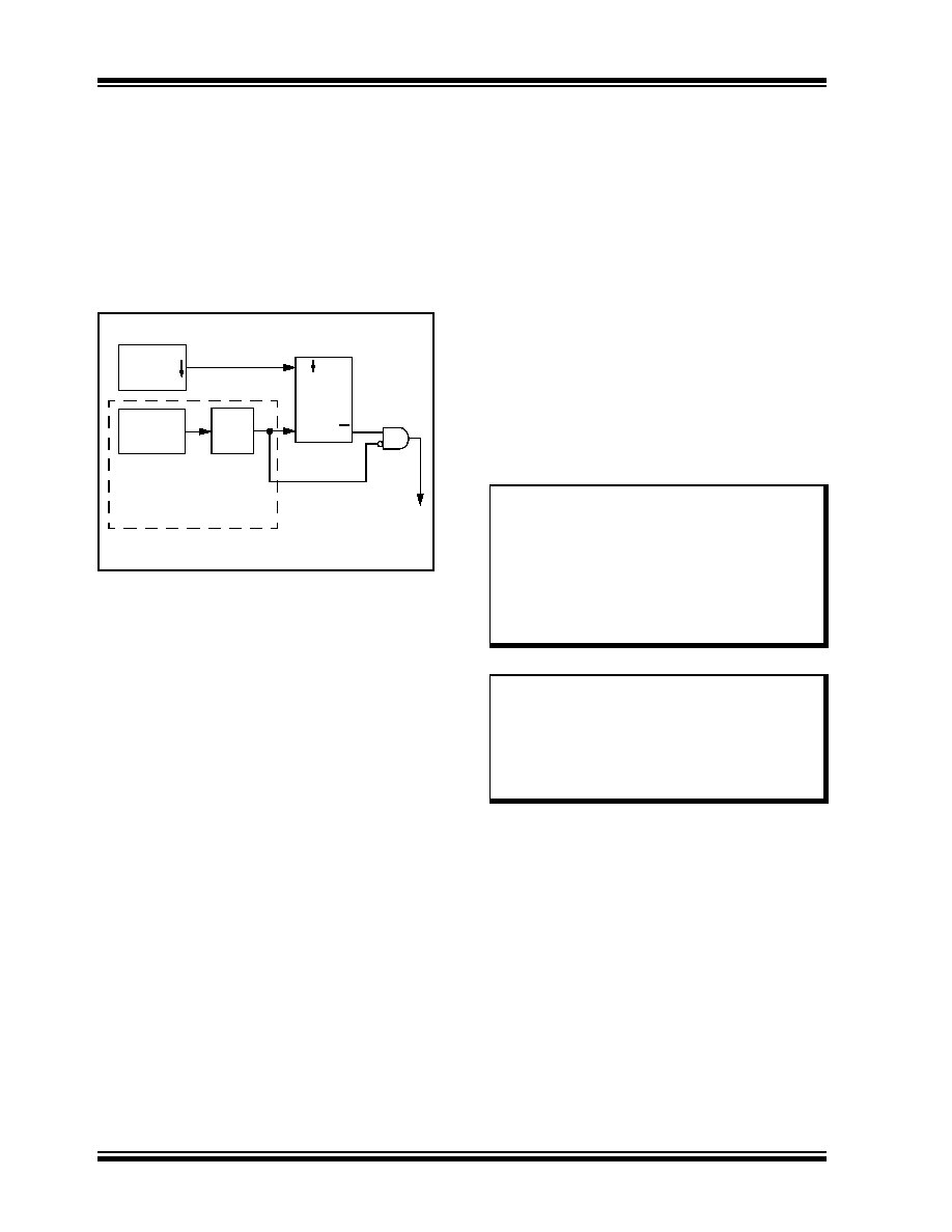
FIGURE 2-10:
FSCM BLOCK DIAGRAM
2.13.1
FAIL-SAFE DETECTION
The FSCM module detects a failed oscillator by
comparing the external oscillator to the FSCM sample
clock. The sample clock is generated by dividing the
LFINTOSC by 64 (see Figure 2-10). Inside the fail
detector block is a latch. The external clock sets the
latch on each falling edge of the external clock. The
sample clock clears the latch on each rising edge of the
sample clock. A failure is detected when an entire half-
cycle of the sample clock elapses before the primary
clock goes low.
2.13.2
FAIL-SAFE OPERATION
When the external clock fails, the FSCM switches the
device clock to an internal clock source and sets the bit
flag OSCFIF of the PIR2 register. The OSCFIF flag will
generate an interrupt if the OSCFIE bit of the PIE2
register is also set. The device firmware can then take
steps to mitigate the problems that may arise from a
failed clock. The system clock will continue to be
sourced from the internal clock source until the device
firmware successfully restarts the external oscillator
and switches back to external operation. An automatic
transition back to the failed clock source will not occur.
The internal clock source chosen by the FSCM is
determined by the IRCF<2:0> bits of the OSCCON
register. This allows the internal oscillator to be
configured before a failure occurs.
2.13.3
FAIL-SAFE CONDITION CLEARING
The Fail-Safe condition is cleared by either one of the
following:
Any Reset
By toggling the SCS1 bit of the OSCCON register
Both of these conditions restart the OST. While the
OST is running, the device continues to operate from
the INTOSC selected in OSCCON. When the OST
times out, the Fail-Safe condition is cleared and the
device automatically switches over to the external clock
source. The Fail-Safe condition need not be cleared
before the OSCFIF flag is cleared.
2.13.4
RESET OR WAKE-UP FROM SLEEP
The FSCM is designed to detect an oscillator failure
after the Oscillator Start-up Timer (OST) has expired.
The OST is used after waking up from Sleep and after
any type of Reset. The OST is not used with the EC or
RC Clock modes so that the FSCM will be active as
soon as the Reset or wake-up has completed. .
External
LFINTOSC
÷ 64
S
R
Q
31 kHz
(~32
s)
488 Hz
(~2 ms)
Clock Monitor
Latch
Clock
Failure
Detected
Oscillator
Clock
Q
Sample Clock
Note:
Due to the wide range of oscillator start-up
times, the Fail-Safe circuit is not active
during oscillator start-up (i.e., after exiting
Reset or Sleep). After an appropriate
amount of time, the user should check the
OSTS bit of the OSCCON register to verify
the oscillator start-up and that the system
clock
switchover
has
successfully
completed.
Note:
When the device is configured for Fail-
Safe clock monitoring in either HS, XT, or
LS Oscillator modes then the IESO config-
uration bit should also be set so that the
clock will automatically switch from the
internal clock to the external oscillator
when the OST times out.
相关PDF资料 |
PDF描述 |
|---|---|
| TS80C51RA2-VCA | IC MCU 8BIT 256BYTE 40MHZ 40-DIP |
| TS80C51RA2-LCA | IC MCU 8BIT 256BYTE 30MHZ 40-DIP |
| PIC18F27J53-I/SP | IC PIC MCU 128KB FLASH 28SPDIP |
| PIC18F66K90-I/PTRSL | MCU PIC 64K FLASH MEM XLP 64TQFP |
| PIC18F67J50-I/PT | IC PIC MCU FLASH 64KX16 64TQFP |
相关代理商/技术参数 |
参数描述 |
|---|---|
| PIC18LF47J13T-I/ML | 功能描述:8位微控制器 -MCU GP 128KB Flash 4KB RAM 12 MIPS 12b ADC RoHS:否 制造商:Silicon Labs 核心:8051 处理器系列:C8051F39x 数据总线宽度:8 bit 最大时钟频率:50 MHz 程序存储器大小:16 KB 数据 RAM 大小:1 KB 片上 ADC:Yes 工作电源电压:1.8 V to 3.6 V 工作温度范围:- 40 C to + 105 C 封装 / 箱体:QFN-20 安装风格:SMD/SMT |
| PIC18LF47J13T-I/PT | 功能描述:8位微控制器 -MCU GP 128KB Flash 4KB RAM 12 MIPS 12b ADC RoHS:否 制造商:Silicon Labs 核心:8051 处理器系列:C8051F39x 数据总线宽度:8 bit 最大时钟频率:50 MHz 程序存储器大小:16 KB 数据 RAM 大小:1 KB 片上 ADC:Yes 工作电源电压:1.8 V to 3.6 V 工作温度范围:- 40 C to + 105 C 封装 / 箱体:QFN-20 安装风格:SMD/SMT |
| PIC18LF47J53-I/ML | 功能描述:8位微控制器 -MCU 128KB Flash 4KB RAM 12MIPS nanoWatt RoHS:否 制造商:Silicon Labs 核心:8051 处理器系列:C8051F39x 数据总线宽度:8 bit 最大时钟频率:50 MHz 程序存储器大小:16 KB 数据 RAM 大小:1 KB 片上 ADC:Yes 工作电源电压:1.8 V to 3.6 V 工作温度范围:- 40 C to + 105 C 封装 / 箱体:QFN-20 安装风格:SMD/SMT |
| PIC18LF47J53-I/PT | 功能描述:8位微控制器 -MCU 128KB Flash 4KB RAM 12MIPS nanoWatt RoHS:否 制造商:Silicon Labs 核心:8051 处理器系列:C8051F39x 数据总线宽度:8 bit 最大时钟频率:50 MHz 程序存储器大小:16 KB 数据 RAM 大小:1 KB 片上 ADC:Yes 工作电源电压:1.8 V to 3.6 V 工作温度范围:- 40 C to + 105 C 封装 / 箱体:QFN-20 安装风格:SMD/SMT |
| PIC18LF47J53T-I/ML | 功能描述:8位微控制器 -MCU USB 128KB Flash 4KB RAM 12 MIPS 12b ADC RoHS:否 制造商:Silicon Labs 核心:8051 处理器系列:C8051F39x 数据总线宽度:8 bit 最大时钟频率:50 MHz 程序存储器大小:16 KB 数据 RAM 大小:1 KB 片上 ADC:Yes 工作电源电压:1.8 V to 3.6 V 工作温度范围:- 40 C to + 105 C 封装 / 箱体:QFN-20 安装风格:SMD/SMT |
发布紧急采购,3分钟左右您将得到回复。