参数资料
| 型号: | PT7C43390WEX |
| 厂商: | Pericom |
| 文件页数: | 18/23页 |
| 文件大小: | 0K |
| 描述: | IC REAL TIME CLOCK 8SOIC |
| 标准包装: | 1 |
| 类型: | 时钟/日历 |
| 特点: | 警报器,闰年,方波输出 |
| 时间格式: | HH:MM:SS(12/24 小时) |
| 数据格式: | YY-MM-DD-dd |
| 接口: | I²C,2 线串口 |
| 电源电压: | 1.3 V ~ 5.5 V |
| 电压 - 电源,电池: | 1.1 V ~ 5.5 V |
| 工作温度: | -40°C ~ 85°C |
| 安装类型: | 表面贴装 |
| 封装/外壳: | 8-SOIC(0.154",3.90mm 宽) |
| 供应商设备封装: | 8-SOIC |
| 包装: | 标准包装 |
| 其它名称: | PT7C43390WEXDKR |
|||||||||||||||||||||||||||||||||||||||||||||||||||||||||||||||||||||||||||||||||||||||||||||||||||||||||||||||||||||||||||||||||||||||||||||||||||||||||||||||||||||||||||||||||||||||||||||||||||||||||||||||||||||||||||||||||||||||||||||||||||||||||||||||||||||||||||||||||||||||||||||||||||||||||||||||||||||||||||||||||||||||
PT0280(08/09)
Ver: 3
4
Data Sheet
PT7C43390
2-Wire Real-time Clock Module
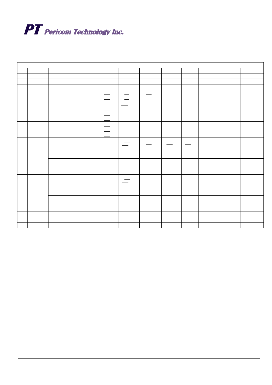
Registers
Allocation of registers
Command
Data
C2 C1 C0
Description
B7
B6
B5
B4
B3
B2
B1
B0
0
Status register_1 access
POC*4
BLD*4
INT2*3
INT1*3
SC1*2
SC0*2
12/24
RESET*1
0
1
Status register_2 access
TEST*5 INT2AE INT2ME INT2FE
32kE
INT1AE INT1ME
INT1FE
0
1
0
Real-time data 1 access
(year data to second
data)
Y80
*6
Y40
*6
AM/PM
m40
s20
Y20
*6
D20
*6
H20
m20
s20
Y10
M10
D10
*6
H10
m10
s10
Y8
M8
D8
*6
H8
m8
s8
Y4
M4
D4
W4
H4
m4
s4
Y2
M2
D2
W2
H2
m2
s2
Y1
M1
D1
W1
H1
m1
s1
0
1
Real-time data 2 access
(hour data to second
data)
*6
AM/PM
m40
s20
H20
m20
s20
H10
m10
s10
H8
m8
s8
H4
m4
s4
H2
m2
s2
H1
m1
s1
INT1 register_1 access
(alarm time 1)
(INT1AE=1,INT1ME=0
INT1FE=0)
A1WE
A1HE
A1mE
*6
AM/PM
m40
*6
H20
m20
*6
H10
m10
*6
H8
m8
W4
H4
m4
W2
H2
m2
W1
H1
m1
1
0
INT1 register_1 access
(frequency duty setting)
(INT1ME=0,INT1FE=1)
SC*7
16Hz
8Hz
4Hz
2Hz
1Hz
INT1 register_2 access
(alarm time 2)
(INT2AE=1,INT2ME=0
INT2FE=0)
A2WE
A2HE
A2mE
*6
AM/PM
m40
*6
H20
m20
*6
H10
m10
*6
H8
m8
W4
H4
m4
W2
H2
m2
W1
H1
m1
1
0
1
INT1 register_2 access
(frequency duty setting)
(INT2ME=0,INT2FE=1)
SC*7
16Hz
8Hz
4Hz
2Hz
1Hz
1
0
Clock adjustment
register access
V7
V6
V5
V4
V3
V2
V1
V0
1
Free register access
F7
F6
F5
F4
F3
F2
F1
F0
Caution:
*1. Write-only flag. By writing “1” to this register, the IC is reset.
*2. Scratch bit. R/W-enabled register that can be freely used by users.
*3. Read-only flag. It is cleared when read. It is valid only when the alarm is set.
*4. Read-only flag. “POC” is set to “1” when power is applied. It is cleared when read. For the “BLD”, refer to “Power Supply Voltage
Detector”.
*5. For IC testing. Normally set this register to “0”.
*6. No effect by writing. It is “0” when read.
*7. This is a R/W-enabled register that does not affect interrupts.
相关PDF资料 |
PDF描述 |
|---|---|
| PT7C4563UEX | IC REAL TIME CLOCK 8MSOP |
| QPI-12LZ-01 | IC INTERFACE FILTER |
| QPI-5LZ | FILTER 24V 14A ACTIVE EMI |
| QPI-6LZ-01 | IC INTERFACE FILTER |
| QPO-1LZ-01 | IC INTERFACE FILTER |
相关代理商/技术参数 |
参数描述 |
|---|---|
| PT7C4363 | 制造商:PERICOM 制造商全称:Pericom Semiconductor Corporation 功能描述:Real-time Clock Module (I2C Bus) |
| PT7C4363P | 制造商:PERICOM 制造商全称:Pericom Semiconductor Corporation 功能描述:Real-time Clock Module (I2C Bus) |
| PT7C4363W | 制造商:PERICOM 制造商全称:Pericom Semiconductor Corporation 功能描述:Real-time Clock Module (I2C Bus) |
| PT7C4363WEX | 制造商:Pericom 功能描述:Real-time Clock Module(I2C Bus) |
| PT7C4372ALE | 制造商:Pericom Semiconductor Corporation 功能描述: |
发布紧急采购,3分钟左右您将得到回复。