- 您现在的位置:买卖IC网 > PDF目录69294 > PWR-82333-120L (DATA DEVICE CORP) BRUSHLESS DC MOTOR CONTROLLER, 50 A, DMA26 PDF资料下载
参数资料
| 型号: | PWR-82333-120L |
| 厂商: | DATA DEVICE CORP |
| 元件分类: | 运动控制电子 |
| 英文描述: | BRUSHLESS DC MOTOR CONTROLLER, 50 A, DMA26 |
| 封装: | 3 X 2.100 INCH, 0.390 INCH HEIGHT, PACKAGE-26 |
| 文件页数: | 15/17页 |
| 文件大小: | 631K |
| 代理商: | PWR-82333-120L |
7
Data Device Corporation
www.ddc-web.com
PWR-82331 and PWR-82333
P-02/05-0
DIGITALLY CONTROLLED INPUTS
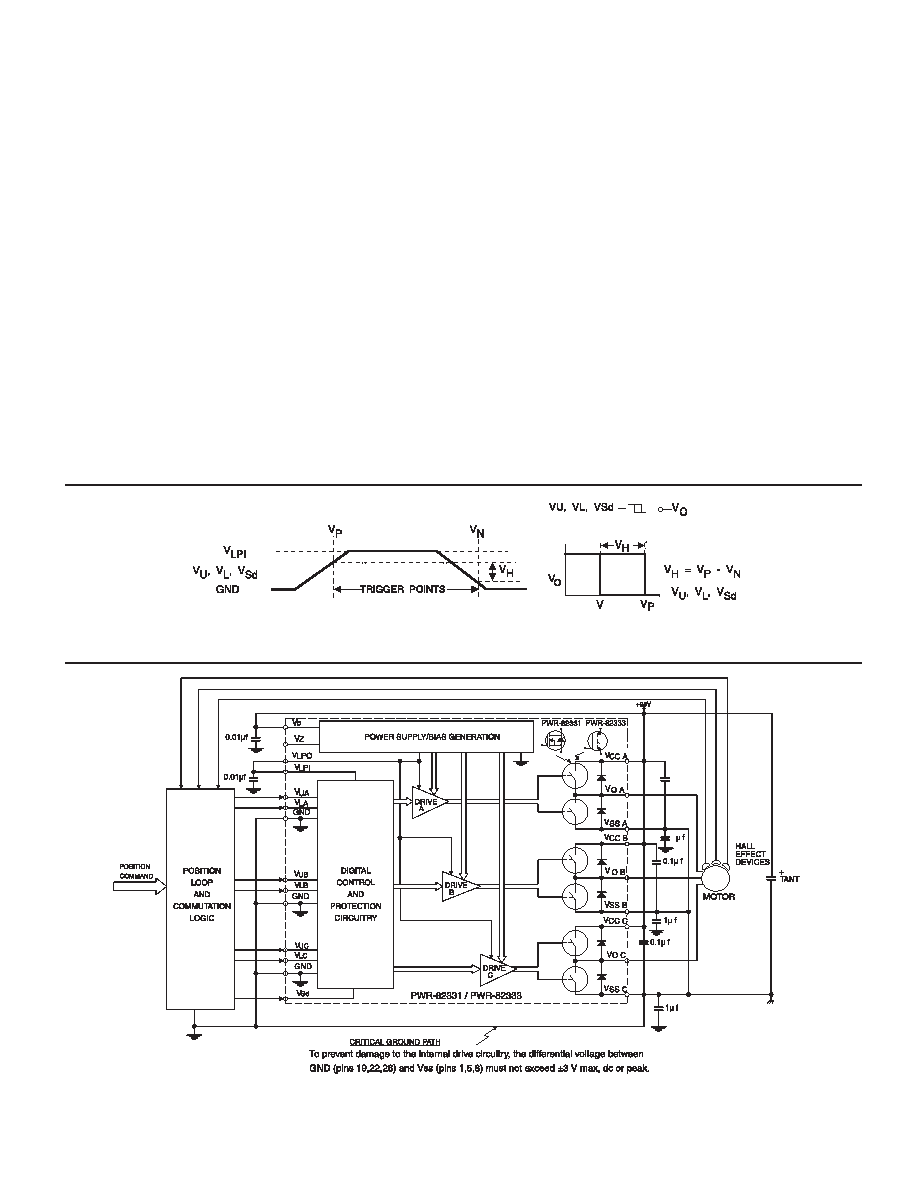
The PWR-82331/82333 uses Schmitt triggered digital inputs
(with hysteresis) to ensure high-noise immunity. The trigger
switches at different points for positive and negative going sig-
nals. The hysteresis voltage (VH) is the difference between the
positive going voltage (VP) and the negative going voltage(VN)
(see FIGURE 7). The digital inputs have programmable logic lev-
els, which allows the hybrid to be used with different types of
commutation logic with an input voltage range of +5 V to +15 V,
such as TTL or CMOS logic. The PWR-82331/82333 internal
power supply generates a +15 Vdc (VLPO) on pin 15. This out-
put can only be used to power the internal digital circuitry within
the hybrid. Do not use this +15 V output to power any circuit-
ry external to the hybrid. Pin 16 is the logic power input (VLPI)
for the digital circuitry inside the hybrid. A 0.01 mF, +50 V ceram-
ic capacitor must be placed between this pin (16) and GND
as close to the hybrid as possible. When using +15 V control
circuitry, the logic power input (pin 16) can be connected direct-
ly to logic power output (pin 15) of the hybrid. There is no need
for an additional external power supply.
When using +5 V control logic, an external +5 Vdc supply
must be connected between pin 16 of the hybrid and the
GND - leave Pin 15 open (N/C). The commutation/control cir-
cuitry can be as simple as discrete logic with PWM, or as sophis-
ticated as a microprocessor or custom ASIC, depending on the
system requirements. The block diagram in FIGURE 8 shows a
typical interface of the PWR-82331/82333 with a motor and com-
mutation logic in a servo-amp system.
INTERFACING WITH OPTOCOUPLERS
Optocouplers should be used when the commutation logic can-
not be located directly next to the motor drive (within 1"- 2" from
the input) or a current sensing resistor is placed between VSS
and POWER RTN (see FIGURE 9). The optocouplers minimize
the differential ground voltage drop between the logic grounds
and the VSS connections. Optocouplers are also required when
+5 V logic is used to control the motor drive.
N
FIGURE 7. HYSTERESIS DEFINITION AND CHARACTERISTICS
0.1
f
1
FIGURE 8. PWR-82331/82333 TYPICAL INTERFACE WITH A MOTOR AND COMMUTATION LOGIC
相关PDF资料 |
PDF描述 |
|---|---|
| PWR-82333-210 | BRUSHLESS DC MOTOR CONTROLLER, 50 A, DMA26 |
| PWR-82333-410Q | BRUSHLESS DC MOTOR CONTROLLER, 50 A, DMA26 |
| PWR-82333-500L | BRUSHLESS DC MOTOR CONTROLLER, 50 A, DMA26 |
| PWR-82331-400S | BRUSHLESS DC MOTOR CONTROLLER, 50 A, DMA26 |
| PWR-82331-810L | BRUSHLESS DC MOTOR CONTROLLER, 50 A, DMA26 |
相关代理商/技术参数 |
参数描述 |
|---|---|
| PWR-82333-200 | 制造商:未知厂家 制造商全称:未知厂家 功能描述:DC Motor Controller/Driver |
| PWR-82333-300 | 制造商:未知厂家 制造商全称:未知厂家 功能描述:DC Motor Controller/Driver |
| PWR-82340 | 制造商:未知厂家 制造商全称:未知厂家 功能描述:Drives (Power Amplifiers)|3-Phase Bridge Drive. Flat Pack Hybrid with Formed Leads |
| PWR-82340-100 | 制造商:未知厂家 制造商全称:未知厂家 功能描述:DC Motor Controller/Driver |
| PWR-82340-110 | 制造商:未知厂家 制造商全称:未知厂家 功能描述:DC Motor Controller/Driver |
发布紧急采购,3分钟左右您将得到回复。