- 您现在的位置:买卖IC网 > PDF目录380636 > R1Q2A3636ABG-40R (Renesas Technology Corp.) 36-Mbit QDR™II SRAM 2-word Burst PDF资料下载
参数资料
| 型号: | R1Q2A3636ABG-40R |
| 厂商: | Renesas Technology Corp. |
| 英文描述: | 36-Mbit QDR™II SRAM 2-word Burst |
| 文件页数: | 4/25页 |
| 文件大小: | 394K |
| 代理商: | R1Q2A3636ABG-40R |
R1Q2A3636/R1Q2A3618/R1Q2A3609
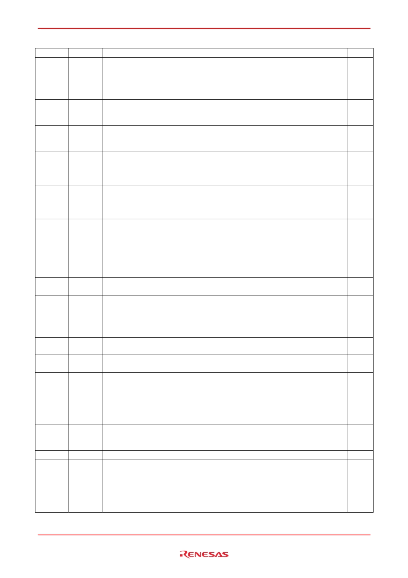
Pin Description
Name
SA
I/O type
Input
Descriptions
Notes
Synchronous address inputs: These inputs are registered and must meet the setup
and hold times around the rising edge of K for READ cycles and must meet the setup
and hold times around the rising edge of /K for WRITE cycles. All transactions operate
on a burst-of-two words (one clock period of bus activity). These inputs are ignored
when device is deselected.
Synchronous read: When low, this input causes the address inputs to be registered
and a READ cycle to be initiated. This input must meet setup and hold times around
the rising edge of K.
Synchronous write: When low, this input causes the address inputs to be registered
and a WRITE cycle to be initiated. This input must meet setup and hold times around
the rising edge of K.
Synchronous byte writes: When low, these inputs cause their respective byte to be
registered and written during WRITE cycles. These signals must meet setup and hold
times around the rising edges of K and /K for each of the two rising edges comprising
the WRITE cycle. See Byte Write Truth Table for signal to data relationship.
Input clock: This input clock pair registers address and control inputs on the rising
edge of K, and registers data on the rising edge of K and the rising edge of /K. /K is
ideally 180 degrees out of phase with K. All synchronous inputs must meet setup and
hold times around the clock rising edges. These balls cannot remain V
REF
level.
Output clock: This clock pair provides a user-controlled means of tuning device output
data. The rising edge of /C is used as the output timing reference for first output data.
The rising edge of C is used as the output timing reference for second output data.
Ideally, /C is 180 degrees out of phase with C. C and /C may be tied high to force the
use of K and /K as the output reference clocks instead of having to provide C and /C
clocks. If tied high, C and /C must remain high and not to be toggled during device
operation. These balls cannot remain V
REF
level.
DLL disable: When low, this input causes the DLL to be bypassed for /DOFF Input
stable, low frequency operation.
Output impedance matching input: This input is used to tune the device outputs to the
system data bus impedance. Q and CQ output impedance are set to 0.2
×
RQ, where
RQ is a resistor from this ball to ground. This ball can be connected directly to V
DDQ
,
which enables the minimum impedance mode. This ball cannot be connected directly
to V
SS
or left unconnected.
IEEE1149.1 test inputs: 1.8 V I/O levels. These balls may be left not TMS Input
connected if the JTAG function is not used in the circuit.
IEEE1149.1 clock input: 1.8 V I/O levels. This ball must be tied to V
SS
if the JTAG
function is not used TCK Input in the circuit.
Synchronous data inputs: Input data must meet setup and hold times around the rising
edges of K and /K during WRITE operations. See Pin Arrangement figures for ball site
location of individual signals.
The
×
9 device uses D0 to D8. Remaining signals are not used.
The
×
18 device uses D0 to D17. Remaining signals are not used.
The
×
36 device uses D0 to D35.
Synchronous echo clock outputs: The edges of these outputs are tightly matched to
the synchronous data outputs and can be used as a data valid indication. These
signals run freely and do not stop when Q tristates.
IEEE 1149.1 test output: 1.8 V I/O level.
Synchronous data outputs: Output data is synchronized to the respective C and /C, or
to the respective K and /K if C and /C are tied high. This bus operates in response to
/R commands. See Pin Arrangement figures for ball site location of individual signals.
The
×
9 device uses Q0 to Q8. Remaining signals are not used.
The
×
18 device uses Q0 to Q17. Remaining signals are not used.
The
×
36 device uses Q0 to Q35.
/R
Input
/W
Input
/BW
x
Input
K, /K
Input
C, /C
Input
/DOFF
Input
ZQ
Input
TMS
TDI
TCK
Input
Input
D
0
to D
n
Input
CQ, /CQ
Output
TDO
Q
0
to Q
n
Output
Output
REJ03C0294-0003 Rev.0.03 Jul. 31, 2007
Page 4 of 23
相关PDF资料 |
PDF描述 |
|---|---|
| R1Q2A3636ABG-50R | 36-Mbit QDR™II SRAM 2-word Burst |
| R1Q2A3636ABG-60R | 36-Mbit QDR™II SRAM 2-word Burst |
| R1Q3A3609 | 36-Mbit QDR™II SRAM 4-word Burst |
| R1Q3A3636ABG-50R | 36-Mbit QDR™II SRAM 4-word Burst |
| R1Q3A3636ABG-60R | 36-Mbit QDR™II SRAM 4-word Burst |
相关代理商/技术参数 |
参数描述 |
|---|---|
| R1Q2A3636ABG40RB0 | 制造商:RENESAS 制造商全称:Renesas Technology Corp 功能描述:36-Mbit QDR?II SRAM 2-word Burst |
| R1Q2A3636ABG40RS0 | 制造商:RENESAS 制造商全称:Renesas Technology Corp 功能描述:36-Mbit QDR?II SRAM 2-word Burst |
| R1Q2A3636ABG40RT0 | 制造商:RENESAS 制造商全称:Renesas Technology Corp 功能描述:36-Mbit QDR?II SRAM 2-word Burst |
| R1Q2A3636ABG-50R | 制造商:RENESAS 制造商全称:Renesas Technology Corp 功能描述:36-Mbit QDR™II SRAM 2-word Burst |
| R1Q2A3636ABG50RB0 | 制造商:RENESAS 制造商全称:Renesas Technology Corp 功能描述:36-Mbit QDR?II SRAM 2-word Burst |
发布紧急采购,3分钟左右您将得到回复。