- 您现在的位置:买卖IC网 > PDF目录69302 > R3F10011NXXXSP MROM, 8 MHz, MICROCONTROLLER, PDSO20 PDF资料下载
参数资料
| 型号: | R3F10011NXXXSP |
| 元件分类: | 微控制器/微处理器 |
| 英文描述: | MROM, 8 MHz, MICROCONTROLLER, PDSO20 |
| 封装: | 4.40 X 6.50 MM, 0.65 MM PITCH, PLASTIC, LSSOP-20 |
| 文件页数: | 12/30页 |
| 文件大小: | 229K |
| 代理商: | R3F10011NXXXSP |
第1页第2页第3页第4页第5页第6页第7页第8页第9页第10页第11页当前第12页第13页第14页第15页第16页第17页第18页第19页第20页第21页第22页第23页第24页第25页第26页第27页第28页第29页第30页
R38F1 Group, R38F2 Group, R38F3 Group
1. Overview
REJ03B0226-0001 Rev.0.01
Nov 21, 2007
Page 2 of 28
Under development Preliminary specification
Notice: This is not a final specification. Some parametric limits are subject to change.
1.1.2
Specifications
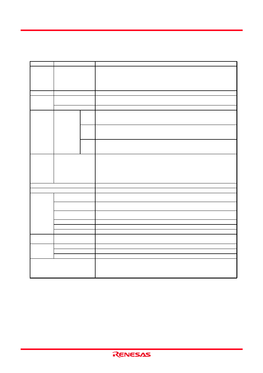
Table 1.1
Specifications for R38F1, R38F2, and R38F3 Groups (1)
Item
Function
Specification
CPU
Central processing
unit
740 Series core
Number of fundamental instructions: 71
Minimum instruction execution time:
0.25
s (f(XIN) = 8 MHz, divided-by-1)
Operating mode: Single-chip mode (address space: 1 Mbyte)
Memory
ROM, RAM
Refer to the product list for each group.
Voltage
Detection
Low-voltage detection
circuit
On-chip
Power-on reset
On-chip
I/O Ports
Programable
I/O
R38F3
Group
CMOS output-only: 1
N-channel open drain output-only: 1
CMOS I/O: 19, selectable pull-up register
R38F2
Group
CMOS output-only: 1
N-channel open drain output-only: 1
CMOS I/O: 15, selectable pull-up register
R38F1
Group
CMOS output-only: 1
N-channel open drain output-only: 1
CMOS I/O: 11, selectable pull-up register
Clock
Clock generation
circuits
3 circuits: XIN clock oscillation circuit (with on-chip feedback resistor),
On-chip oscillator (high-speed, low-speed),
XCIN clock oscillation circuit (32 kHz, with on-chip feedback resistor)
Oscillation stop detection: XIN clock oscillation stop detection function
Frequency divider circuit: Division ratio selectable from 1, 2, 4, and 8
Low-power-consumption modes: Wait mode, stop mode
Interrupts
External: 4 sources, Internal: 8 sources, Software: 1 source
Watchdog Timer
16 bits × 1 channel
Timer
Timer 1
8 bits × 1 (with 8-bit prescaler shared with timer 1 and timer 2)
Timer mode (period timer)
Timer 2
8 bits × 1 (with 8-bit prescaler shared with timer 1 and timer 2)
Timer mode (period timer, inverted level output per cycle)
Timer A
16 bits × 1 (with timer A (high-order, low-order) latch)
Timer mode (period timer)
Timer C
15 bits × 1
Output compare
3 channels (timer A used)
Input capture
1 channel (timer A used)
Serial
Interface
Serial I/O1
Clock synchronous serial I/O/UART I/O × 1
A/D
Converter
R38F3 Group
10-bit resolution × 8 channels
R38F2 Group
10-bit resolution × 6 channels
R38F1 Group
10-bit resolution × 4 channels
Flash Memory
Programming and erasure voltage: VCC = 5.0 V
Programming and erasure endurance: 10 times
Programming security: ROM code protection
Operating mode of flash memory: 1 mode (standard serial I/O)
相关PDF资料 |
PDF描述 |
|---|---|
| R42181 | SINGLE COLOR LED, RED, 5.6 mm |
| R42182 | SINGLE COLOR LED, RED, 5.6 mm |
| S42182H | SINGLE COLOR LED, NATURAL WHITE, 5.6 mm |
| R432035 | SPECIALTY MICROPROCESSOR CIRCUIT, CQCC68 |
| R432057 | DRAM CONTROLLER, CQCC68 |
相关代理商/技术参数 |
参数描述 |
|---|---|
| R3FBAUZ | 功能描述:XLR 连接器 R/ANGLE XLR 3 FEMAL RoHS:否 制造商:Neutrik 标准:Standard XLR 产品类型:Connectors 型式:Female 位置/触点数量:3 端接类型:Solder 安装风格:Cable 方向:Vertical |
| R3FL | 制造商:Switchcraft 功能描述:Conn XLR Connector F 3 POS RA Cable Mount 3 Terminal 1 Port |
| R3FPKG | 制造商:Switchcraft 功能描述:R3F IN PLASTIC BAG/ |
| R3F-RS | 制造商:Switchcraft 功能描述:3way r/a XLR cable plug w/skt contact15A |
| R3FZ | 功能描述:XLR 连接器 3P F R/A W/STRN RLF RoHS:否 制造商:Neutrik 标准:Standard XLR 产品类型:Connectors 型式:Female 位置/触点数量:3 端接类型:Solder 安装风格:Cable 方向:Vertical |
发布紧急采购,3分钟左右您将得到回复。