- 您现在的位置:买卖IC网 > PDF目录378128 > RDA012M4-DI (Electronic Theatre Controls, Inc.) 12 Bit 1.3 GS/s 4:1 MUXDAC PDF资料下载
参数资料
| 型号: | RDA012M4-DI |
| 厂商: | Electronic Theatre Controls, Inc. |
| 英文描述: | 12 Bit 1.3 GS/s 4:1 MUXDAC |
| 中文描述: | 12位1.3 GS / s的4:1 MUXDAC |
| 文件页数: | 4/12页 |
| 文件大小: | 392K |
| 代理商: | RDA012M4-DI |
RDA012M4 DATASHEET
DS_0012PB1-2805
Rockwell Scientific reserves the right to make changes to its product specifications at any time without notice.
The information furnished herein is believed to be accurate; however, no responsibility is assumed for its use.
Page 4 of 12
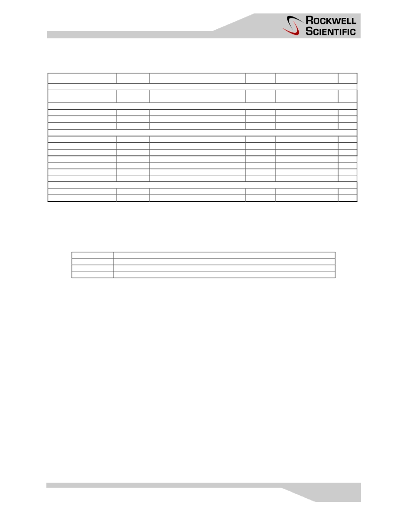
Electrical Specification
PARAMETER
TERMINATION (VTT)
HCLKI Termination
Voltage
REFERENCE (VREFA, VREFD)
Analog Reference
Digital Reference
Input Resistance
POWER SUPPLY
Positive Supply
Negative Supply, Analog
Negative Supply, Digital
Power Dissipation
Power Dissipation
Power Dissipation
Power Dissipation
OPERATING RANGE
Ambient Temperature
Junction Temperature
SYMBOL
CONDITIONS, NOTE
TEST LEVEL
MIN
TYP
MAX UNITS
VTT
-2.0
V
VREFA
VREFD
R
VREF
Internally generated
Internally generated
For externally driven VREFA, VREFD
3
3
3
-1.9
-1.9
500
-2.0
-2.0
560
-2.1
-2.1
620
V
V
VCC
VEEA
VEED
P
P
VCC
P
VEEA
P
VEED
3.1
-5.4
-5.4
3.3
-5.2
-5.2
3300
500
500
2300
3.5
-5.0
-5.0
V
V
V
Total dissipation
Positive supply
Negative supply, analog
Negative supply, digital
mW
mW
mW
mW
T
A
T
J
°C
°C
120
Test Levels
TEST LEVEL
1
2
3
TEST PROCEDURE
100% production tested at T
A
= 25C
1,2
Sample tested at T
A
= 25C unless other temperature is specified
1
Guaranteed by design and/or characterization testing
1
All tests are continuous, not pulsed. Therefore, Tj (junction temperature) > Tc (case temperature) > Ta (ambient temperature).
This is the normal operating condition and is more stressful than a pulsed test condition.
2
The tests are conducted with the power set to VCC
MIN
and to VCC
MAX
.
相关PDF资料 |
PDF描述 |
|---|---|
| RDA012M4-HD | 12 Bit 1.3 GS/s 4:1 MUXDAC |
| RDL60V | RESETABLE FUSES |
| RDL60V010 | RESETABLE FUSES |
| RDL60V017 | RESETABLE FUSES |
| RDL60V185 | RESETABLE FUSES |
相关代理商/技术参数 |
参数描述 |
|---|---|
| RDA012M4-HD | 制造商:未知厂家 制造商全称:未知厂家 功能描述:12 Bit 1.3 GS/s 4:1 MUXDAC |
| RDA012M4MS | 制造商:未知厂家 制造商全称:未知厂家 功能描述:12 Bit 1.3 GS/s Master-Slave 4:1 MUXDAC |
| RDA012M4MS-DI | 制造商:未知厂家 制造商全称:未知厂家 功能描述:12 Bit 1.3 GS/s Master-Slave 4:1 MUXDAC |
| RDA012M4MS-HD | 制造商:未知厂家 制造商全称:未知厂家 功能描述:12 Bit 1.3 GS/s Master-Slave 4:1 MUXDAC |
| RDA1005LTR7 | 制造商:RF Micro Devices Inc 功能描述:IC AMP DVGA 32-MCM 5.2X5.2 |
发布紧急采购,3分钟左右您将得到回复。