- 您现在的位置:买卖IC网 > PDF目录66140 > RLD65NZT1 655 nm, LASER DIODE PDF资料下载
参数资料
| 型号: | RLD65NZT1 |
| 元件分类: | 激光器 |
| 英文描述: | 655 nm, LASER DIODE |
| 文件页数: | 2/4页 |
| 文件大小: | 73K |
| 代理商: | RLD65NZT1 |
RLD65NZT1
Laser Diodes
2/3
!
Absolute maximum ratings (Tc=25
°C)
Parameter
PO
VR
VR(PIN)
Tstg
Topr
mW
V
Symbol
7
2
30
10 to +70
40 to +85
Limits
Unit
°C
Output
Raser
Operating temperature
Storage temperature
PIN photodiode
Reverse
voltage
!
Electrical and optical characteristics (Tc=25
°C)
Parameter
Symbol
Min.
Typ.
Max.
Unit
Conditions
Ith
mA
25
60
Iop
mA
35
70
PO
=5mW
PO
=5mW
PO
=5mW
PO
=5mW
PO
=5mW
PO
=5mW
PO
=5mW
Im
mA
0.1
0.2
0.5
θ //
deg
78
10
θ ⊥
deg
20
27
35
φ //
deg
20
+2
λ
nm
645
655
660
PO
=5mW
Astigmatism
m
10
PO
=5mW
φ ⊥
deg
30
+3
Y
Z
X
m
80
0
+80
Vop
V
2.3
2.6
η
mW/mA
0.2
0.4
0.8
θ // and θ ⊥ are defined as the angle within which the intensity is 50% of the peak value.
Threshold current
Operating current
Monitor current
Parallel divergence angle
Perpendicular divergence angle
Parallel deviation angle
Peak emission wavelength
Perpendicular deviation angle
Emission point accuracy
Operating voltage
Differential efficiency
!
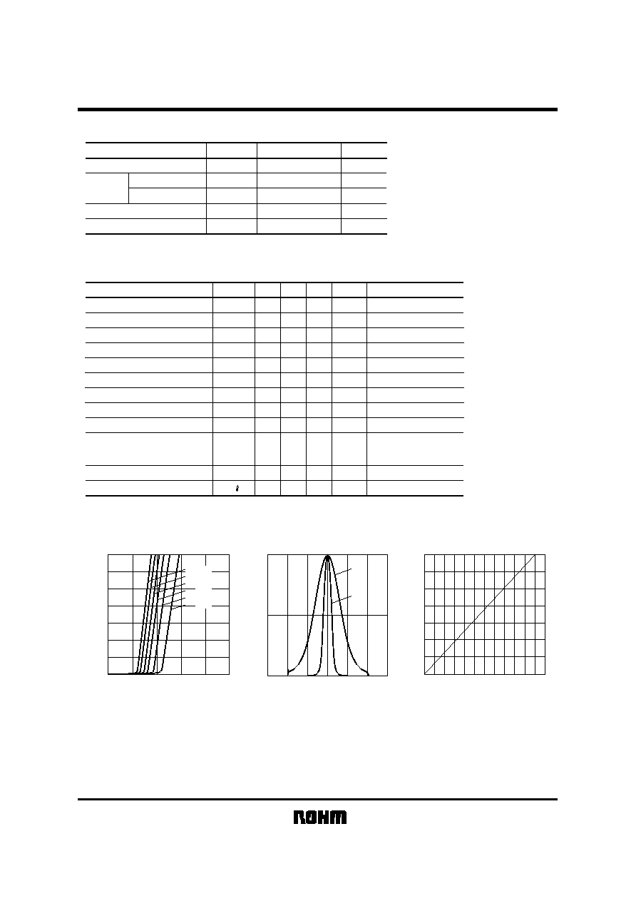
Electrical and optical characteristics curves
7
6
4
5
3
1
2
0
20406080
100
OPTICAL
PO
WER
:
P
O
(mW)
OPERATING CURRENT : Iop
(mA)
Tc
=25°C
40
°C
50
°C
60
°C
70
°C
80
°C
Fig.1 Optical output
vs. operating current
1.0
0.5
0
60
40
20
0
60
40
20
INTENSITY
ANGLE (
deg)
θ ⊥
θ //
Fig.2 Far field pattern
7
1
2
3
4
5
6
0
0.1
0.2
0.3
OPTICAL
INTENSITY
:
P
O
(mW)
MONITOR CURRENT : Im (mA)
Fig.3 Monitor current
vs. optical output
相关PDF资料 |
PDF描述 |
|---|---|
| RLD78MPA1 | 785 nm, LASER DIODE |
| RLD78MRA1 | 785 nm, LASER DIODE |
| RLD78MYA1 | 785 nm, LASER DIODE |
| RLD78MZGM | 785 nm, LASER DIODE |
| RLD78NZC3 | 785 nm, LASER DIODE |
相关代理商/技术参数 |
参数描述 |
|---|---|
| RLD-65PC | 制造商:ROHM Semiconductor 功能描述: |
| RLD65PZB5 | 制造商:ROHM 制造商全称:Rohm 功能描述:DVD-Record, High power red laser diode |
| RLD-78MA | 制造商:ROHM 制造商全称:Rohm 功能描述:AlGaAs laser diodes |
| RLD-78MA5 | 制造商:未知厂家 制造商全称:未知厂家 功能描述:Laser Diodes |
| RLD-78MAT1 | 制造商:ROHM 制造商全称:Rohm 功能描述:AlGaAs laser diodes |
发布紧急采购,3分钟左右您将得到回复。