- 您现在的位置:买卖IC网 > PDF目录18781 > RXM-900-HP3-PPO_ (Linx Technologies Inc)RECEIVER RF 900MHZ 8-CHANNEL PDF资料下载
参数资料
| 型号: | RXM-900-HP3-PPO_ |
| 厂商: | Linx Technologies Inc |
| 文件页数: | 7/13页 |
| 文件大小: | 0K |
| 描述: | RECEIVER RF 900MHZ 8-CHANNEL |
| 产品变化通告: | Internal Component Change 25/Aug/2011 |
| 标准包装: | 10 |
| 系列: | HP3 |
| 频率: | 902MHz ~ 928MHz |
| 灵敏度: | -100dBm |
| 数据传输率 - 最大: | 56 kbps |
| 调制或协议: | FM,FSK |
| 应用: | 家庭/工业自动化,远程访问,安全警报 |
| 电流 - 接收: | 18mA |
| 数据接口: | PCB,通孔 |
| 天线连接器: | 通孔 |
| 特点: | 多通道,模拟和数字数据 |
| 电源电压: | 2.8 V ~ 13 V |
| 工作温度: | -30°C ~ 85°C |
| 封装/外壳: | 18-SIP |
| 供应商设备封装: | 18-SIP |
| 包装: | 管件 |
| 其它名称: | RXM-900-HP3-PPO_-ND |
�� �
�
�PROTOCOL� GUIDELINES�
�While� many� RF� solutions� impose� data� formatting� and� balancing� requirements,�
�Linx� RF� modules� do� not� encode� or� packetize� the� signal� content� in� any� manner.�
�The� received� signal� will� be� affected� by� such� factors� as� noise,� edge� jitter,� and�
�interference,� but� it� is� not� purposefully� manipulated� or� altered� by� the� modules.�
�This� gives� the� designer� tremendous� flexibility� for� protocol� design� and� interface.�
�TYPICAL� APPLICATIONS�
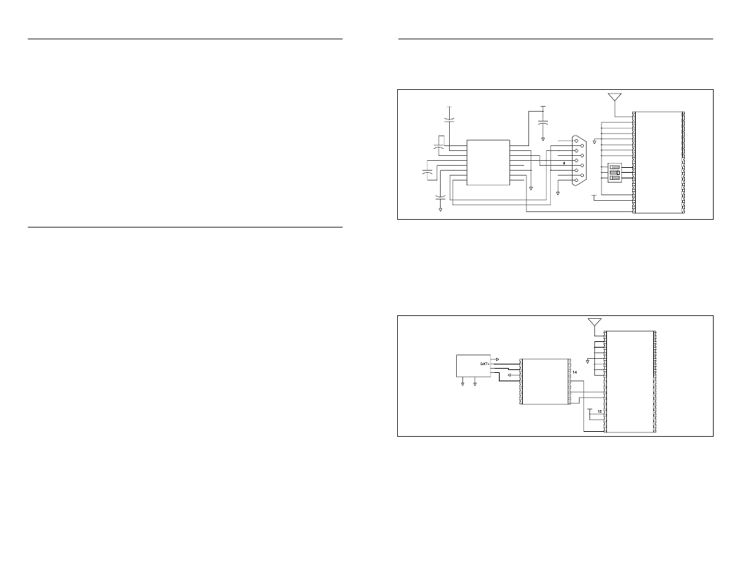
�The� figure� below� shows� a� typical� RS-232� circuit� using� the� HP3� Series� receiver�
�and� a� Maxim� MAX232.� The� receiver� outputs� a� serial� data� stream� and� the�
�MAX232� converts� that� to� RS-232� compliant� signals.� The� MODE� line� is� grounded�
�so� the� channels� are� selected� by� the� DIP� switches.�
�Despite� this� transparency� and� ease� of� use,� it� must� be� recognized� that� there� are�
�VCC�
�VCC�
�distinct� differences� between� a� wired� and� a� wireless� environment.� Issues� such� as�
�interference� and� contention� must� be� understood� and� allowed� for� in� the� design�
�C1�
�4.7uF�
�+� C2�
�4.7uF�
�1�
�2�
�3�
�ANT�
�GND�
�GND�
�NC�
�NC�
�NC�
�36�
�35�
�34�
�process.� To� learn� more� about� protocol� considerations,� we� suggest� you� read� Linx�
�Application� Note� AN-00160.�
�Errors� from� interference� or� changing� signal� conditions� can� cause� corruption� of�
�the� data� packet,� so� it� is� generally� wise� to� structure� the� data� being� sent� into� small�
�packets.� This� allows� errors� to� be� managed� without� affecting� large� amounts� of�
�data.� A� simple� checksum� or� CRC� could� be� used� for� basic� error� detection.� Once�
�an� error� is� detected,� the� protocol� designer� may� wish� to� simply� discard� the� corrupt�
�data� or� implement� a� more� sophisticated� scheme� to� correct� it.�
�C4�
�4.7uF�
�C3�
�4.7uF�
�+�
�C5�
�4.7uF�
�+�
�1�
�2�
�3�
�4�
�5�
�6�
�7�
�8�
�C1+�
�V+�
�C1-�
�C2+�
�C2-�
�V-�
�T2OUT�
�R2IN�
�MAX232�
�VCC�
�GND�
�T1OUT�
�R1IN�
�R1OUT�
�T1IN�
�T2IN�
�R2OUT�
�16�
�15�
�14�
�13�
�12�
�11�
�10�
�9�
�GND�
�GND�
�GND�
�1�
�6�
�2�
�7�
�3�
�4�
�9�
�5�
�DB-� 9�
�GND�
�VCC�
�4�
�5�
�6�
�7�
�8�
�9�
�10�
�11�
�12�
�13�
�14�
�15�
�16�
�17�
�18�
�GND�
�GND�
�GND�
�GND�
�GND�
�NC�
�CS0�
�CS1� /� SS� CLOCK�
�CS2� /� SS� DATA�
�PDN�
�RSSI�
�MODE�
�VCC�
�AUDIO�
�DATA�
�NC�
�NC�
�NC�
�NC�
�NC�
�NC�
�NC�
�NC�
�NC�
�NC�
�NC�
�NC�
�NC�
�NC�
�NC�
�33�
�32�
�31�
�30�
�2� 9�
�28�
�27�
�26�
�25�
�24�
�23�
�22�
�21�
�20�
�1� 9�
�INTERFERENCE� CONSIDERATIONS�
�The� RF� spectrum� is� crowded� and� the� potential� for� conflict� with� other� unwanted�
�sources� of� RF� is� very� real.� While� all� RF� products� are� at� risk� from� interference,� its�
�effects� can� be� minimized� by� better� understanding� its� characteristics.�
�Interference� may� come� from� internal� or� external� sources.� The� first� step� is� to�
�eliminate� interference� from� noise� sources� on� the� board.� This� means� paying�
�careful� attention� to� layout,� grounding,� filtering,� and� bypassing� in� order� to�
�eliminate� all� radiated� and� conducted� interference� paths.� For� many� products,� this�
�is� straightforward;� however,� products� containing� components� such� as� switching�
�power� supplies,� motors,� crystals,� and� other� potential� sources� of� noise� must� be�
�GND�
�Figure� 14:� HP3� Receiver� and� MAX232� IC�
�The� figure� below� shows� a� circuit� using� the� QS� Series� USB� module.� The� QS�
�converts� the� data� from� the� receiver� into� USB� compliant� signals� to� be� sent� to� a�
�PC.� The� MODE� line� is� high,� so� the� module� is� in� Serial� Channel� Select� mode.� The�
�RTS� and� DTR� lines� are� used� to� load� the� channels.� Application� Note� AN-00155�
�shows� sample� source� code� that� can� be� adapted� to� use� on� a� PC.� The� QS� Series�
�Data� Guide� and� Application� Note� AN-00200� discuss� the� hardware� and� software�
�set-up� required� for� QS� Series� modules.�
�approached� with� care.� Comparing� your� own� design� with� a� Linx� evaluation� board�
�can� help� to� determine� if� and� at� what� level� design-specific� interference� is� present.�
�1�
�2�
�3�
�ANT�
�GND�
�GND�
�NC�
�NC�
�NC�
�36�
�35�
�34�
�External� interference� can� manifest� itself� in� a� variety� of� ways.� Low-level�
�interference� will� produce� noise� and� hashing� on� the� output� and� reduce� the� link’s�
�overall� range.�
�USB-B�
�GND�
�DAT� -�
�5V�
�4�
�3�
�2�
�1�
�GND�
�GND�
�1�
�2�
�3�
�4�
�USBDP� RI�
�USBDM� DCD�
�GND� DSR�
�VCC� DATA_IN�
�16�
�15�
�13�
�GND�
�4�
�5�
�6�
�7�
�8�
�9�
�GND�
�GND�
�GND�
�GND�
�GND�
�NC�
�NC�
�NC�
�NC�
�NC�
�NC�
�NC�
�33�
�32�
�31�
�30�
�2� 9�
�28�
�High-level� interference� is� caused� by� nearby� products� sharing� the� same�
�frequency� or� from� near-band� high-power� devices.� It� can� even� come� from� your�
�GND�
�GND�
�5�
�6�
�7�
�8�
�SUSP_IND� DATA_OUT�
�RX_IND� RTS�
�TX_IND�
�CTS�
�485_TX�
�DTR�
�12�
�11�
�10�
�9�
�10�
�11�
�12�
�13�
�CS0�
�CS1� /� SS� CLOCK�
�CS2� /� SS� DATA�
�PDN�
�NC�
�NC�
�NC�
�NC�
�27�
�26�
�25�
�24�
�own� products� if� more� than� one� transmitter� is� active� in� the� same� area.� It� is�
�important� to� remember� that� only� one� transmitter� at� a� time� can� occupy� a�
�frequency,� regardless� of� the� coding� of� the� transmitted� signal.� This� type� of�
�SDM-USB-QS�
�VCC� 14�
�16�
�17�
�18�
�RSSI�
�MODE�
�VCC�
�AUDIO�
�DATA�
�NC�
�NC�
�NC�
�NC�
�NC�
�23�
�22�
�21�
�20�
�1� 9�
�interference� is� less� common� than� those� mentioned� previously,� but� in� severe�
�cases� it� can� prevent� all� useful� function� of� the� affected� device.�
�Although� technically� it� is� not� interference,� multipath� is� also� a� factor� to� be�
�understood.� Multipath� is� a� term� used� to� refer� to� the� signal� cancellation� effects�
�that� occur� when� RF� waves� arrive� at� the� receiver� in� different� phase� relationships.�
�This� effect� is� a� particularly� significant� factor� in� interior� environments� where�
�objects� provide� many� different� signal� reflection� paths.� Multipath� cancellation�
�results� in� lowered� signal� levels� at� the� receiver� and,� thus,� shorter� useful� distances�
�for� the� link.�
�Page� 12�
�Figure� 15:� HP3� Receiver� and� Linx� QS� Series� USB� Module�
�The� receiver� can� also� be� connected� to� a� microcontroller,� which� will� interpret� the�
�data� and� take� specific� actions.� A� UART� may� be� employed� or� an� I� /� O� line� may� be�
�used� to� continuously� monitor� the� DATA� line� for� a� valid� packet.� The� receiver� may�
�be� connected� directly� to� the� microcontroller� without� the� need� for� buffering� or�
�amplification.�
�Page� 13�
�相关PDF资料 |
PDF描述 |
|---|---|
| RXM-900-HP3-PPS_ | RECEIVER RF 900MHZ 8PAR/120SRLCH |
| RXM-900-HP3-SPO_ | RECEIVER RF 900MHZ 8-CH SMD |
| RXM-GPS-SG-B | GPS MODULE SMD SIRF |
| RXM-916-ES_ | RECEIVER RF 916MHZ 16PIN SMD |
| RXD-315-KH2 | RECEIVER RF 315MHZ SMT KH2 SER |
相关代理商/技术参数 |
参数描述 |
|---|---|
| RXM-900-HP3-PPO_ | 功能描述:RECEIVER RF 900MHZ 8-CHANNEL RoHS:是 类别:RF/IF 和 RFID >> RF 接收器 系列:HP3 产品培训模块:Lead (SnPb) Finish for COTS 产品变化通告:Product Discontinuation 09/Jan/2012 标准包装:50 系列:* 频率:850MHz ~ 2.175GHz 灵敏度:- 数据传输率 - 最大:- 调制或协议:- 应用:* 电流 - 接收:* 数据接口:PCB,表面贴装 存储容量:- 天线连接器:PCB,表面贴装 特点:- 电源电压:4.75 V ~ 5.25 V 工作温度:0°C ~ 85°C 封装/外壳:40-WFQFN 裸露焊盘 供应商设备封装:40-TQFN-EP(6x6) 包装:托盘 |
| RXM-900-HP3-PPS | 功能描述:射频模块 RF Receiver 900MHz 8 & 100-CH SIP Pack RoHS:否 制造商:Linx Technologies 产品:Transceiver Modules 频带:902 MHz to 928 MHz 输出功率:- 15.5 dBm to + 12.5 dBm 接口类型:UART 工作电源电压:- 0.3 VDC to + 5.5 VDC 传输供电电流:38.1 mA 接收供电电流:22.7 mA 天线连接器类型:U.FL 最大工作温度:+ 85 C 尺寸:1.15 mm x 0.63 mm x 0.131 mm |
| RXM-900-HP3-PPS_ | 功能描述:RECEIVER RF 900MHZ 8PAR/120SRLCH RoHS:是 类别:RF/IF 和 RFID >> RF 接收器 系列:HP3 产品培训模块:Lead (SnPb) Finish for COTS 产品变化通告:Product Discontinuation 09/Jan/2012 标准包装:50 系列:* 频率:850MHz ~ 2.175GHz 灵敏度:- 数据传输率 - 最大:- 调制或协议:- 应用:* 电流 - 接收:* 数据接口:PCB,表面贴装 存储容量:- 天线连接器:PCB,表面贴装 特点:- 电源电压:4.75 V ~ 5.25 V 工作温度:0°C ~ 85°C 封装/外壳:40-WFQFN 裸露焊盘 供应商设备封装:40-TQFN-EP(6x6) 包装:托盘 |
| RXM-900-HP3-SPO | 功能描述:射频模块 RF Receiver 900MHz 8-CH SMD Pack RoHS:否 制造商:Linx Technologies 产品:Transceiver Modules 频带:902 MHz to 928 MHz 输出功率:- 15.5 dBm to + 12.5 dBm 接口类型:UART 工作电源电压:- 0.3 VDC to + 5.5 VDC 传输供电电流:38.1 mA 接收供电电流:22.7 mA 天线连接器类型:U.FL 最大工作温度:+ 85 C 尺寸:1.15 mm x 0.63 mm x 0.131 mm |
| RXM-900-HP3-SPO_ | 功能描述:RECEIVER RF 900MHZ 8-CH SMD RoHS:是 类别:RF/IF 和 RFID >> RF 接收器 系列:- 产品培训模块:Lead (SnPb) Finish for COTS 产品变化通告:Product Discontinuation 09/Jan/2012 标准包装:50 系列:* 频率:850MHz ~ 2.175GHz 灵敏度:- 数据传输率 - 最大:- 调制或协议:- 应用:* 电流 - 接收:* 数据接口:PCB,表面贴装 存储容量:- 天线连接器:PCB,表面贴装 特点:- 电源电压:4.75 V ~ 5.25 V 工作温度:0°C ~ 85°C 封装/外壳:40-WFQFN 裸露焊盘 供应商设备封装:40-TQFN-EP(6x6) 包装:托盘 |
发布紧急采购,3分钟左右您将得到回复。