- 您现在的位置:买卖IC网 > PDF目录40071 > SB130 (SENSITRON SEMICONDUCTOR) 1 A, 30 V, SILICON, SIGNAL DIODE, DO-41 PDF资料下载
参数资料
| 型号: | SB130 |
| 厂商: | SENSITRON SEMICONDUCTOR |
| 元件分类: | 二极管(射频、小信号、开关、功率) |
| 英文描述: | 1 A, 30 V, SILICON, SIGNAL DIODE, DO-41 |
| 封装: | PLASTIC PACKAGE-2 |
| 文件页数: | 1/3页 |
| 文件大小: | 149K |
| 代理商: | SB130 |
SB120 – SB160
1.0A SCHOTTKY BARRIER RECTIFIER
Data Sheet 3061, Rev. —
Features
Schottky Barrier Chip
Guard Ring Die Construction for
Transient Protection
High Current Capability
A
B
A
Low Power Loss, High Efficiency
High Surge Current Capability
For Use in Low Voltage, High Frequency
Inverters, Free Wheeling, and Polarity
Protection Applications
C
D
Mechanical Data
Case: Molded Plastic
Terminals: Plated Leads Solderable per
MIL-STD-202, Method 208
Polarity: Cathode Band
Weight: 0.34 grams (approx.)
Mounting Position: Any
Marking: Type Number
Maximum Ratings and Electrical Characteristics @T
A=25°C unless otherwise specified
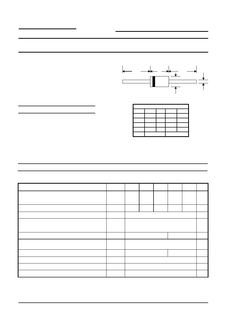
DO-41
Dim
Min
Max
Min
Max
A
25.4
—
1.000
—
B
4.06
5.21
0.159
0.205
C
0.71
0.864 0.028
0.034
D
2.00
2.72
0.079
0.107
In mm
In inch
Single Phase, half wave, 60Hz, resistive or inductive load.
For capacitive load, derate current by 20%.
Characteristic
Symbol
SB120
SB130
SB140
SB150
SB160
Unit
Peak Repetitive Reverse Voltage
Working Peak Reverse Voltage
DC Blocking Voltage
VRRM
VRWM
VR
20
30
40
50
60
V
RMS Reverse Voltage
VR(RMS)
14
21
28
35
42
V
Average Rectified Output Current
(Note 1)
@TL = 100°C
IO
1.0
A
Non-Repetitive Peak Forward Surge Current 8.3ms
Single half sine-wave superimposed on rated load
(JEDEC Method)
IFSM
40
A
Forward Voltage
@IF = 1.0A
VFM
0.50
0.70
V
Peak Reverse Current
@TA = 25°C
At Rated DC Blocking Voltage
@TA = 100°C
IRM
0.5
10
mA
Typical Junction Capacitance (Note 2)
Cj
110
80
pF
Typical Thermal Resistance Junction to Lead
RθJL
15
K/W
Typical Thermal Resistance Junction to Ambient (Note 1)
RθJA
50
K/W
Operating and Storage Temperature Range
Tj, TSTG
-65 to +150
°C
N
2. Measured at 1.0 MHz and applied reverse voltage of 4.0V D.C.
ote: 1. Valid provided that leads are kept at ambient temperature at a distance of 9.5mm from the case.
SENSITRON
SEMICONDUCTOR
�
!
! !!"#$
%&'(&)*+,,---.&
./012&%#
%3&
./0
相关PDF资料 |
PDF描述 |
|---|---|
| SB150 | 1 A, 50 V, SILICON, SIGNAL DIODE, DO-41 |
| SB120-G | 1 A, 20 V, SILICON, SIGNAL DIODE, DO-41 |
| SB140-B | 1 A, SILICON, SIGNAL DIODE |
| MBR1050 | 10 A, SILICON, RECTIFIER DIODE |
| MBR1090 | 10 A, SILICON, RECTIFIER DIODE |
相关代理商/技术参数 |
参数描述 |
|---|---|
| SB130 _AY _10001 | 制造商:PanJit Touch Screens 功能描述: |
| SB130 | 制造商:Vishay Semiconductors 功能描述:DIODE SCHOTTKY 1A 30V |
| SB130/1 | 制造商:Vishay Angstrohm 功能描述:Diode Schottky 30V 1A 2-Pin DO-204AL Bulk |
| SB130_ R2 _10001 | 制造商:PanJit Touch Screens 功能描述: |
| SB1305100ML | 制造商:ABC 制造商全称:ABC Taiwan Electronics Corp 功能描述:SMD POWER INDUCTOR |
发布紧急采购,3分钟左右您将得到回复。