- 您现在的位置:买卖IC网 > PDF目录192920 > SF400CE40E RELAY SOCKET PDF资料下载
参数资料
| 型号: | SF400CE40E |
| 元件分类: | 插座 |
| 英文描述: | RELAY SOCKET |
| 文件页数: | 8/13页 |
| 文件大小: | 920K |
| 代理商: | SF400CE40E |
NUMBERING SYSTEM
SERIES F470
F470
B
4
A
P AND/OR XXX
Basic series designation__________________________|
|
1-Mounting Styles (A,B,C,D,J,K,H)_____________________|
|
2-Terminal Types(1,2,4,8)_________________________________|
|
3-Coil Voltage (C,H,B,J,A,D,E,W,V)____________________________|
|
4-Coil Suppression (P)_____________________________________________|
|
5-Coding keys for H mounting style___________________________________________|
NOTES
1. Relays with B, D mounting styles and terminal type 4 are compatible with socket SF400CE40E.
2. Relays with H mounting style are compatible with socket SF400-1F.
3. Isolation spacer pads for PCB mounting available on request.
4. For other mounting styles or terminal types or coding, please contact factory.
5. Non overlapping arrangement insures that if one of the NO or NC contacts is accidentally welded, none of
the other contacts can be transfered to another state.
6. For "H" mount relays with coil suppression, customer should specify the code.
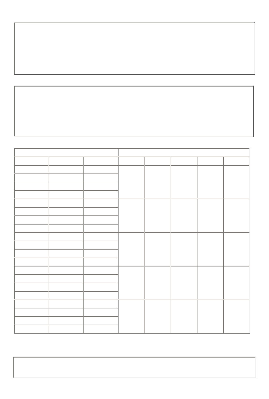
CODING CHART FOR H MOUNTING WITHOUT COIL SUPPRESSION (5)
Type of contact operation
Nominal load voltage
pole
low level
high level
24 volts
48 volts
72 volts
110 volts
36 volts
A
X
UUU
VUU
WUU
XUU
YUU
B
X
C
X
D
X
A
X
UVU
VVU
WVU
XVU
YVU
B
X
C
X
D
X
A
X
UWU
VWU
WWU
XWU
YWU
B
X
C
X
D
X
A
X
UXU
VXU
WXU
XXU
YXU
B
X
C
X
D
X
A
X
UYU
VYU
WYU
XYU
YYU
B
X
C
X
D
X
TYPICAL CHARACTERISTICS
q
Coil resistance temperature change: See application note n°001
q
Coil L/R ratio for all types of DC coils is = 11 ms
Date of issue: 4/06
- 16 -
Page 4 of 4
相关PDF资料 |
PDF描述 |
|---|---|
| SF402-1F | RELAY SOCKET |
| SF402CE40E | RELAY SOCKET |
| SF50N13 | 78.5 A, 1000 V, SCR |
| SF50Q13 | 78.5 A, 1200 V, SCR |
| SF50D13 | 78.5 A, 200 V, SCR |
相关代理商/技术参数 |
参数描述 |
|---|---|
| SF400-G | 功能描述:INTELLIGENT SMS SERVER 4PORT RoHS:是 类别:计算机,办公室 - 元件,配件 >> 集线器,服务器 系列:MultiModem® iSMS 标准包装:1 系列:MultiConnect™ SE 类型:服务器,串行至以太网 特点:- 尺寸:3.50" L X 2.10" W x 0.98" H(88.9mm x 53.3mm x 24.9mm) 适用于相关产品:- |
| SF400G26 | 制造商:未知厂家 制造商全称:未知厂家 功能描述:1600V 400A |
| SF400J26 | 制造商:未知厂家 制造商全称:未知厂家 功能描述:1600V 400A |
| SF400L26 | 制造商:未知厂家 制造商全称:未知厂家 功能描述:1600V 400A |
| SF400L4B1 | 制造商:未知厂家 制造商全称:未知厂家 功能描述:FLAT PACKAGE THYRISTOR STACK |
发布紧急采购,3分钟左右您将得到回复。