- 您现在的位置:买卖IC网 > Datasheet目录46 > SG6932SZ (Fairchild Semiconductor)IC PFC CONTROLLER CCM 16SOP Datasheet资料下载
参数资料
| 型号: | SG6932SZ |
| 厂商: | Fairchild Semiconductor |
| 文件页数: | 13/20页 |
| 文件大小: | 919K |
| 描述: | IC PFC CONTROLLER CCM 16SOP |
| 标准包装: | 2,500 |
| 模式: | 连续导电(CCM) |
| 频率 - 开关: | 65kHz |
| 电流 - 启动: | 10µA |
| 电源电压: | 14 V ~ 20 V |
| 工作温度: | -40°C ~ 85°C |
| 安装类型: | 表面贴装 |
| 封装/外壳: | 16-SOIC(0.154",3.90mm 宽) |
| 供应商设备封装: | 16-SOIC |
| 包装: | 带卷 (TR) |
?2007 Fairchild Semiconductor Corporation
www.fairchildsemi.com
SG6932 " Rev. 1.1.3
13
Functional Description
The highly integrated SG6932 is designed for power
supplies with boost PFC and forward PWM. It requires
very few external components to achieve versatile
protections and compensation.
The
proprietary
interleave-switching
feature
synchronizes the PFC and PWM stages and reduces
switching noise. At light load, the switching frequency is
linearly decreased to reduce power consumption.
The PFC function is implemented by average-current-
mode control. The proprietary switching charge
multiplier-divider provides a high degree of noise
immunity for the PFC circuit. This enables the PFC
circuit to operate over a much wider region. The
proprietary multi-vector output voltage control scheme
provides a fast transient response in a low-bandwidth
PFC loop; in which the overshoot and undershoot of
the PFC voltage are clamped. If the feedback loop; is
broken, the SG6932 shuts off PFC to prevent extra-
high voltage on output.
For the forward PWM, the synchronized slope
compensation ensures the stability of the current loop
under continuous-mode operation. Hiccup operation
during output overloading is guaranteed. To prevent the
power supply from drawing large current during start-
up, the start-up for PWM stage is delayed 4ms after the
PFC output voltage reaches its set value.
SG6932 provides complete protection functions, such
as brownout protection and built-in latch for over-
voltage and RI open/short.
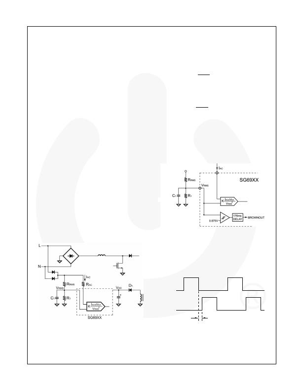
I
AC
Signal
Figure 24 shows the IAC pin connected to input voltage
by a resistor and the current, I
AC,
is the input for PFC
multiplier. For the linear range of I
AC
0~360糀, the
range input voltage should be connected to a
resistance over 1.2M?
Figure 24. Input Voltage Detection
Switching Frequency / Current Sources
The switching frequency can be programmed by the
resistor R
I
connected between the RI and GND pins.
The relationship is:
( )
)
kHz
(
k&
R
1560
f
I
PWM
=
(1)
For example, a 24k& resistor R
I
results in a 65kHz
switching frequency. Accordingly, constant current I
T
flows through R
I
:
(mA)
)
k
(
R
V
2
.
1
I
I
T
?/DIV>
=
(2)
I
T
is used to generate internal current reference.
Line Voltage Detection (VRMS)
Figure 25 shows a resistive divider with low-pass
filtering for line-voltage detection on the VRMS pin. The
V
RMS
voltage is used for the PFC multiplier and
brownout protection. For brownout protection, when the
V
RMS
voltage drops below 0.8V, OPFC turns off.
0.47礔~4.7礔
Figure 25. Line-Voltage Detection on VRMS Pin
Interleave Switching
The SG6932 uses interleaved switching to synchronize
the PFC and PWM stages. This reduces switching
noise and spreads the EMI emissions. Figure 26 shows
off-time (t
OFF
) inserted between the turn-off of the PFC
gate drives and the turn-on of the PWM.
Figure 26. Interleaved Switching
OPFC
OPWM
TOFF
t
OFF
相关PDF资料 |
PDF描述 |
|---|---|
| SG6961SY | IC PFC CTRLR AVERAGE CURR 8SOIC |
| SI3500-A-GM | IC POE SWITCH PWR OVER LAN 20QFN |
| SI786LSG-E3 | IC REG QD BUCK/LINEAR 28SSOP |
| SIC417CD-T1-E3 | IC REG DL BCK/LINEAR SYNC 32MLPQ |
| SP619EK-L/TR | IC HIGH CURRENT SW SOT23-6 |
相关代理商/技术参数 |
参数描述 |
|---|---|
| SG6961 | 制造商:FAIRCHILD 制造商全称:Fairchild Semiconductor 功能描述:Power Factor Controller |
| SG6961BSTA_DBB14 WAF | 制造商:Fairchild Semiconductor Corporation 功能描述: |
| SG6961DZ | 功能描述:功率因数校正 IC Grn Mode PFC/Forward PWM Controller RoHS:否 制造商:Fairchild Semiconductor 开关频率:300 KHz 最大功率耗散: 最大工作温度:+ 125 C 安装风格:SMD/SMT 封装 / 箱体:SOIC-8 封装:Reel |
| SG6961SY | 功能描述:功率因数校正 IC Power Factor Controller RoHS:否 制造商:Fairchild Semiconductor 开关频率:300 KHz 最大功率耗散: 最大工作温度:+ 125 C 安装风格:SMD/SMT 封装 / 箱体:SOIC-8 封装:Reel |
| SG6961SZ | 功能描述:功率因数校正 IC Power Factor Controller RoHS:否 制造商:Fairchild Semiconductor 开关频率:300 KHz 最大功率耗散: 最大工作温度:+ 125 C 安装风格:SMD/SMT 封装 / 箱体:SOIC-8 封装:Reel |
发布紧急采购,3分钟左右您将得到回复。