- 您现在的位置:买卖IC网 > Datasheet目录46 > SG6932SZ (Fairchild Semiconductor)IC PFC CONTROLLER CCM 16SOP Datasheet资料下载
参数资料
| 型号: | SG6932SZ |
| 厂商: | Fairchild Semiconductor |
| 文件页数: | 14/20页 |
| 文件大小: | 919K |
| 描述: | IC PFC CONTROLLER CCM 16SOP |
| 标准包装: | 2,500 |
| 模式: | 连续导电(CCM) |
| 频率 - 开关: | 65kHz |
| 电流 - 启动: | 10µA |
| 电源电压: | 14 V ~ 20 V |
| 工作温度: | -40°C ~ 85°C |
| 安装类型: | 表面贴装 |
| 封装/外壳: | 16-SOIC(0.154",3.90mm 宽) |
| 供应商设备封装: | 16-SOIC |
| 包装: | 带卷 (TR) |
?2007 Fairchild Semiconductor Corporation
www.fairchildsemi.com
SG6932 " Rev. 1.1.3
14
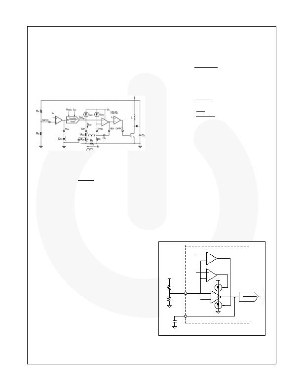
PFC Operation
The purpose of a boost active power factor corrector
(PFC) is to shape the input current of a power supply.
The input current waveform and phase follow that of the
input voltage. Average-current-mode control is utilized
for continuous-current-mode operation for the PFC
booster. With the innovative multi-vector control for
voltage loop and switching charge multiplier-divider for
current reference, excellent input power factor is
achieved with good noise immunity and transient
response. Figure 27 shows the control loop for the
average-current-mode control circuit.
Figure 27. Control Loop of PFC Stage
The current source output from the switching charge
multiplier-divider can be expressed as:
A)
(?/SPAN>
2
RMS
EA
AC
MO
V
V
I
K
I
?/DIV>
?/DIV>
=
(3)
I
MP
, the current output from IMP pin, is the summation
of I
MO
and I
MR1
. I
MR1
and I
MR2
are identical, fixed-current
sources. R
2
and R
3
are also identical and are used to
pull HIGH the operating point of the IMP and IPFC pins
when the voltage across R
S
goes negative with respect
to ground.
Through the differential amplification of the signal
across R
S
, better noise immunity is achieved. The
output of IEA is compared with an internal sawtooth
and the pulsewidth for PFC is determined. Through the
average-current-mode control loop, the input current I
S
is proportional to I
MO
:
S
S
2
MO
R
I
R
I
?/DIV>
=
?/DIV>
(4)
According to Equation 4, the minimum value of R
2
and
maximum of R
S
can be determined because I
MO
should
not exceed the specified maximum value.
There are different considerations in determining the
value of the sense resistor R
S
. The value of R
S
should
be small enough to reduce power consumption, but
large enough to maintain the resolution. A current
transformer (CT) may be used to improve the efficiency
of high-power converters.
To achieve good power factor, the voltage for V
RMS
and
V
EA
should be kept as DC as possible, according to
Equation 3. Good RC filtering for V
RMS
and narrow
bandwidth (lower than the line frequency) for voltage
loop are suggested for better input current shaping.
The transconductance error amplifier has output
impedance R
O
(>90k? and a capacitor C
EA
(1糉 ~
10糉) connected to ground (as shown in Figure 28).
This establishes a dominant pole f
1
for the voltage loop:
EA
O
1
C
R
2
1
f
?/DIV>
?/DIV>
=
?/DIV>
(5)
The average total input power can be expressed as:
EA
2
RMS
EA
AC
IN
RMS
2
RMS
EA
AC
RMS
MO
RMS
IN
IN
IN
V
V
V
R
V
V
V
V
I
V
I
V
)
rms
(
I
)
rms
(
V
P
?/DIV>
?/DIV>
?/DIV>
?/DIV>
?/DIV>
?/DIV>
=
(6)
From Equation 6, V
EA
, the output of the voltage error
amplifier, actually controls the total input power and the
power delivered to the load.
Multi-vector Error Amplifier
The voltage-loop error amplifier is transconductance,
which has high output impedance (> 90k?. A capacitor
C
EA
(1糉 ~ 10糉) connected from VEA to ground
provides a dominant pole for the voltage loop. Although
the PFC stage has a low bandwidth voltage loop for
better input power factor, the innovative multi-vector
error amplifier provides a fast transient response to
clamp the overshoot and undershoot of the PFC output
voltage.
Figure 28 shows the block diagram of the multi-vector
error amplifier. When the variation of the feedback
voltage exceeds ?% of the reference voltage, the
transconductance error amplifier adjusts its output
impedance to increase the loop response. If R
A
is
opened, SG6932 shuts off immediately to prevent
extra-high voltage on the output capacitor.
FBPFC
VEA
RA
RB
K
IACxVEA
VRMS
2
SG69XX
3.15V
3V
2.85V
CEA
+
-
+
-
Figure 28. Multi-Vector Error Amplifier
相关PDF资料 |
PDF描述 |
|---|---|
| SG6961SY | IC PFC CTRLR AVERAGE CURR 8SOIC |
| SI3500-A-GM | IC POE SWITCH PWR OVER LAN 20QFN |
| SI786LSG-E3 | IC REG QD BUCK/LINEAR 28SSOP |
| SIC417CD-T1-E3 | IC REG DL BCK/LINEAR SYNC 32MLPQ |
| SP619EK-L/TR | IC HIGH CURRENT SW SOT23-6 |
相关代理商/技术参数 |
参数描述 |
|---|---|
| SG6961 | 制造商:FAIRCHILD 制造商全称:Fairchild Semiconductor 功能描述:Power Factor Controller |
| SG6961BSTA_DBB14 WAF | 制造商:Fairchild Semiconductor Corporation 功能描述: |
| SG6961DZ | 功能描述:功率因数校正 IC Grn Mode PFC/Forward PWM Controller RoHS:否 制造商:Fairchild Semiconductor 开关频率:300 KHz 最大功率耗散: 最大工作温度:+ 125 C 安装风格:SMD/SMT 封装 / 箱体:SOIC-8 封装:Reel |
| SG6961SY | 功能描述:功率因数校正 IC Power Factor Controller RoHS:否 制造商:Fairchild Semiconductor 开关频率:300 KHz 最大功率耗散: 最大工作温度:+ 125 C 安装风格:SMD/SMT 封装 / 箱体:SOIC-8 封装:Reel |
| SG6961SZ | 功能描述:功率因数校正 IC Power Factor Controller RoHS:否 制造商:Fairchild Semiconductor 开关频率:300 KHz 最大功率耗散: 最大工作温度:+ 125 C 安装风格:SMD/SMT 封装 / 箱体:SOIC-8 封装:Reel |
发布紧急采购,3分钟左右您将得到回复。