- 您现在的位置:买卖IC网 > PDF目录16512 > SI3056SSI-EVB (Silicon Laboratories Inc)BOARD EVAL SI3056/SI3018 SSI PDF资料下载
参数资料
| 型号: | SI3056SSI-EVB |
| 厂商: | Silicon Laboratories Inc |
| 文件页数: | 49/94页 |
| 文件大小: | 0K |
| 描述: | BOARD EVAL SI3056/SI3018 SSI |
| 标准包装: | 1 |
| 主要目的: | 电信,数据采集装置(DAA) |
| 已用 IC / 零件: | Si3056 |
| 已供物品: | 板,CD |
第1页第2页第3页第4页第5页第6页第7页第8页第9页第10页第11页第12页第13页第14页第15页第16页第17页第18页第19页第20页第21页第22页第23页第24页第25页第26页第27页第28页第29页第30页第31页第32页第33页第34页第35页第36页第37页第38页第39页第40页第41页第42页第43页第44页第45页第46页第47页第48页当前第49页第50页第51页第52页第53页第54页第55页第56页第57页第58页第59页第60页第61页第62页第63页第64页第65页第66页第67页第68页第69页第70页第71页第72页第73页第74页第75页第76页第77页第78页第79页第80页第81页第82页第83页第84页第85页第86页第87页第88页第89页第90页第91页第92页第93页第94页
Si3056
Si3018/19/10
Rev. 1.05
53
Reset settings = 0000_0000
1
DLCSI
Delta Loop Current Sense Interrupt
0 = The LCS bits have not changed value.
1 = The LCS bits have changed value; a hardware interrupt occurs on the AOUT/INT pin. This bit
must be written to a 0 to be cleared.
0
POLI
Polarity Reversal Detect Interrupt.
0 = Bit 7 of the LVS register does not change states.
1 = Bit 7 of the LVS register changes from a 0 to a 1, or from a 1 to a 0, indicating the polarity of
TIP and RING is switched. If the POLM and INTE bits are set, a hardware interrupt occurs on the
AOUT/INT pin. To clear the interrupt, write this bit to 0.
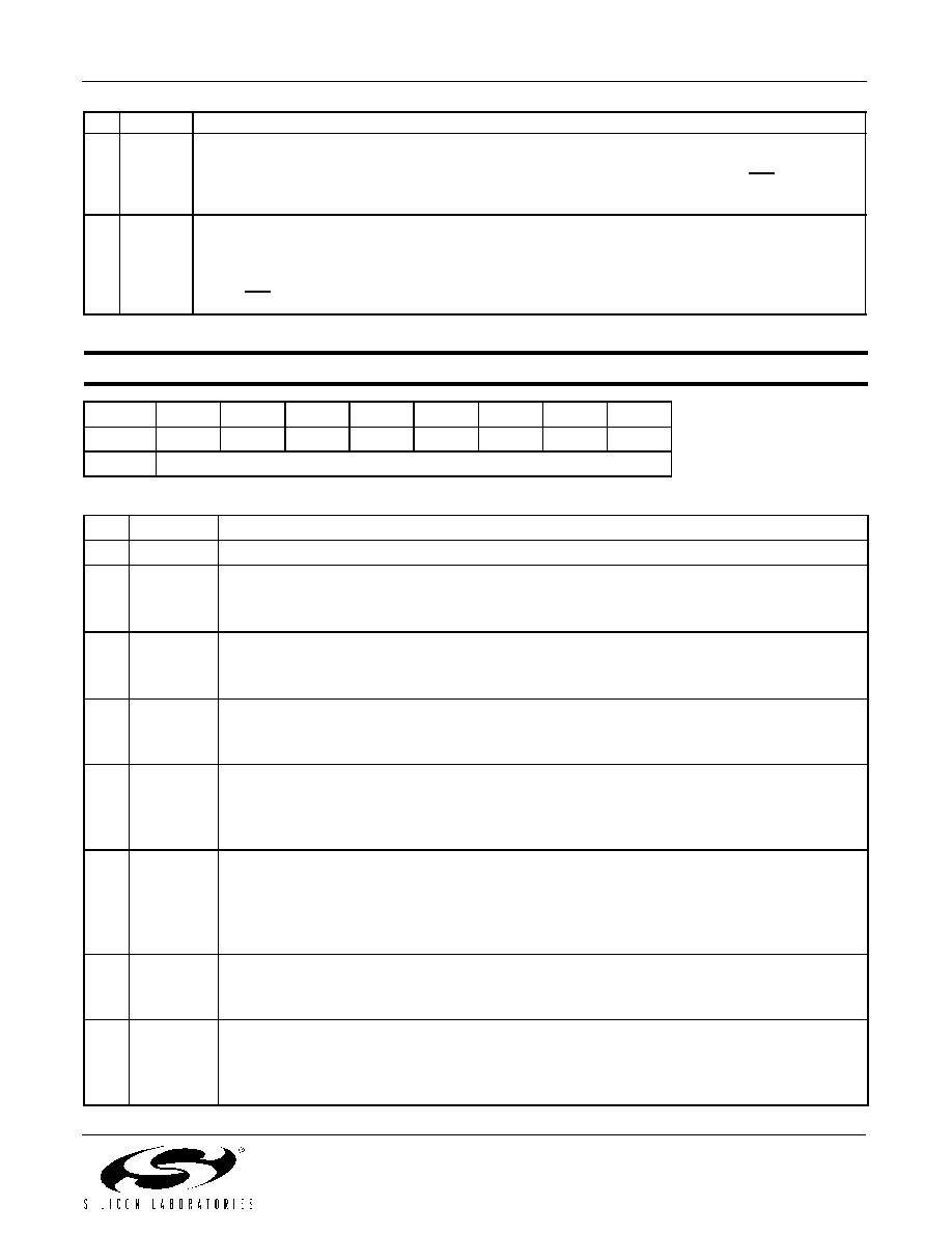
Register 5. DAA Control 1
Bit
D7D6D5D4D3D2D1
D0
Name
RDTN
RDTP
OPOL
ONHM
RDT
OHE
OH
Type
R
R/W
R
R/W
Bit
Name
Function
7
Reserved Read returns zero.
6
RDTN
Ring Detect Signal Negative.
0 = No negative ring signal is occurring.
1 = A negative ring signal is occurring.
5RDTP
Ring Detect Signal Positive.
0 = No positive ring signal is occurring.
1 = A positive ring signal is occurring.
4OPOL
Off-hook Polarity.
0 = Off-hook pin is active low.
1 = Off-hook pin is active high.
3ONHM
On-Hook Line Monitor.
0 = Normal on-hook mode.
1 = Enables low-power on-hook monitoring mode allowing the host to receive line activity
without going off-hook. This mode is used for caller-ID detection.
2
RDT
Ring Detect.
0 = Reset either 5 seconds after last positive ring is detected or when the system executes an
off-hook. Only a positive ring sets this bit when RFWE = 0. When RFWE = 1, either a positive
or negative ring sets this bit.
1 = Indicates a ring is occurring.
1OHE
Off-hook Pin Enable.
0 = Off-hook pin is ignored.
1 = Enables operation of the off-hook pin.
0OH
Off-Hook.
0 = Line-side device on-hook.
1 = Causes the line-side device to go off-hook. This bit operates independently of the OHE bit
and is a logic OR with the off-hook pin when enabled.
Bit
Name
Function
相关PDF资料 |
PDF描述 |
|---|---|
| S1812R-223K | INDUCTOR SHIELDED 22UH SMD |
| ILSB1206ER8R2K | INDUCTOR 8.2UH 10% 1206 |
| GEM36DTKN-S288 | CONN EDGECARD 72POS .156 EXTEND |
| 1-5503995-8 | CA 62.5/125UM ZIP OMCER14 |
| XR19L210IL40-0B-EB | EVAL BOARD FOR XR19L202 40QFN |
相关代理商/技术参数 |
参数描述 |
|---|---|
| SI3056-X-FS | 制造商:SILABS 制造商全称:SILABS 功能描述:GLOBAL SERIAL INTERFACE DIRECT ACCESS ARRANGEMENT |
| SI3060 | 制造商:未知厂家 制造商全称:未知厂家 功能描述:GLOBAL LINE-SIDE DAA FOR EMBEDDED SYSTEM-SIDE MODULE |
| SI3060-X-FS | 制造商:未知厂家 制造商全称:未知厂家 功能描述:GLOBAL LINE-SIDE DAA FOR EMBEDDED SYSTEM-SIDE MODULE |
| SI3060-X-FSR | 制造商:未知厂家 制造商全称:未知厂家 功能描述:GLOBAL LINE-SIDE DAA FOR EMBEDDED SYSTEM-SIDE MODULE |
| SI3060-X-FT | 制造商:未知厂家 制造商全称:未知厂家 功能描述:GLOBAL LINE-SIDE DAA FOR EMBEDDED SYSTEM-SIDE MODULE |
发布紧急采购,3分钟左右您将得到回复。