- 您现在的位置:买卖IC网 > Datasheet目录356 > SI8405AB-A-IS1 (Silicon Laboratories Inc)IC ISOLATOR 10M 6CH 2.5K 16SOIC Datasheet资料下载
参数资料
| 型号: | SI8405AB-A-IS1 |
| 厂商: | Silicon Laboratories Inc |
| 文件页数: | 14/34页 |
| 文件大小: | 0K |
| 描述: | IC ISOLATOR 10M 6CH 2.5K 16SOIC |
| 视频文件: | Digital Isolation Overview Digital Isolators vs. Optocouplers |
| 标准包装: | 48 |
| 输入 - 1 侧/2 侧: | 3/3 |
| 通道数: | 6 |
| 电源电压: | 3 V ~ 5.5 V |
| 电压 - 隔离: | 2500Vrms |
| 数据速率: | 10Mbps |
| 传输延迟: | 20ns |
| 输出类型: | 开路漏极 |
| 封装/外壳: | 16-SOIC(0.154",3.90mm 宽) |
| 供应商设备封装: | 16-SOIC N |
| 包装: | 管件 |
| 工作温度: | -40°C ~ 125°C |
第1页第2页第3页第4页第5页第6页第7页第8页第9页第10页第11页第12页第13页当前第14页第15页第16页第17页第18页第19页第20页第21页第22页第23页第24页第25页第26页第27页第28页第29页第30页第31页第32页第33页第34页
�� �
�
�Si840x�
�3.3.� Layout� Recommendations�
�To� ensure� safety� in� the� end� user� application,� high� voltage� circuits� (i.e.,� circuits� with� >30� V� AC� )� must� be� physically�
�separated� from� the� safety� extra-low� voltage� circuits� (SELV� is� a� circuit� with� <30� V� AC� )� by� a� certain� distance�
�(creepage/clearance).� If� a� component,� such� as� a� digital� isolator,� straddles� this� isolation� barrier,� it� must� meet� those�
�creepage/clearance� requirements� and� also� provide� a� sufficiently� large� high-voltage� breakdown� protection� rating�
�(commonly� referred� to� as� working� voltage� protection).� Table� 6� on� page� 9� and� Table� 7� on� page� 9� detail� the� working�
�voltage� and� creepage/clearance� capabilities� of� the� Si84xx.� These� tables� also� detail� the� component� standards�
�(UL1577,� IEC60747,� CSA� 5A),� which� are� readily� accepted� by� certification� bodies� to� provide� proof� for� end-system�
�specifications� requirements.� Refer� to� the� end-system� specification� (61010-1,� 60950-1,� etc.)� requirements� before�
�starting� any� design� that� uses� a� digital� isolator.�
�The� following� sections� detail� the� recommended� bypass� and� decoupling� components� necessary� to� ensure� robust�
�overall� performance� and� reliability� for� systems� using� the� Si84xx� digital� isolators.�
�3.3.1.� Supply� Bypass�
�Digital� integrated� circuit� components� typically� require� 0.1� μF� (100� nF)� bypass� capacitors� when� used� in� electrically�
�quiet� environments.� However,� digital� isolators� are� commonly� used� in� hazardous� environments� with� excessively�
�noisy� power� supplies.� To� counteract� these� harsh� conditions,� it� is� recommended� that� an� additional� 1� μF� bypass�
�capacitor� be� added� between� VDD� and� GND� on� both� sides� of� the� package.� The� capacitors� should� be� placed� as�
�close� as� possible� to� the� package� to� minimize� stray� inductance.� If� the� system� is� excessively� noisy,� it� is�
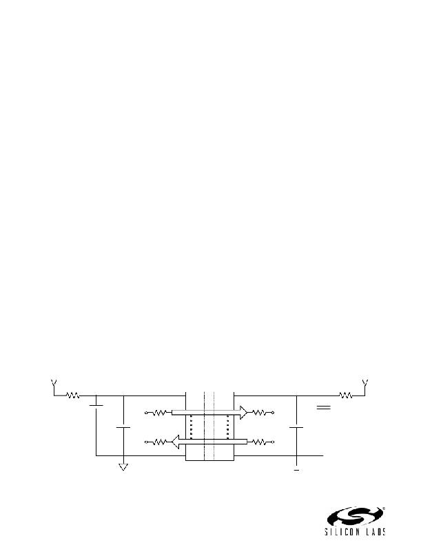
�recommended� that� the� designer� add� 50� to� 100� ?� resistors� in� series� with� the� VDD� supply� voltage� source� and� 50� to�
�300� ?� resistors� in� series� with� the� digital� inputs/outputs� (see� Figure� 8).� For� more� details,� see� "5.Errata� and� Design�
�Migration� Guidelines"� on� page� 22.�
�All� components� upstream� or� downstream� of� the� isolator� should� be� properly� decoupled� as� well.� If� these� components�
�are� not� properly� decoupled,� their� supply� noise� can� couple� to� the� isolator� inputs� and� outputs,� potentially� causing�
�damage� if� spikes� exceed� the� maximum� ratings� of� the� isolator� (6� V).� In� this� case,� the� 50� to� 300� ?� resistors� protect�
�the� isolator's� inputs/outputs� (note� that� permanent� device� damage� may� occur� if� the� absolute� maximum� ratings� are�
�exceeded).� Functional� operation� should� be� restricted� to� the� conditions� specified� in� Table� 3,� “Si8400/01/02/05�
�Electrical� Characteristics� for� Bidirectional� I2C� Channels� 1� ,”� on� page� 5.� and� Table� 4,� “Electrical� Characteristics� for�
�Unidirectional� Non-I2C� Digital� Channels� (Si8402/05),”� on� page� 7�
�3.3.2.� Pin� Connections�
�No� connect� pins� are� not� internally� connected.� They� can� be� left� floating,� tied� to� V� DD� ,� or� tied� to� GND.�
�3.3.3.� Output� Pin� Termination�
�The� nominal� output� impedance� of� an� non-I� 2� C� isolator� driver� channel� is� approximately� 85� ?� ,� ±40%,� which� is� a�
�combination� of� the� value� of� the� on-chip� series� termination� resistor� and� channel� resistance� of� the� output� driver� FET.�
�When� driving� loads� where� transmission� line� effects� will� be� a� factor,� output� pins� should� be� appropriately� terminated�
�with� controlled� impedance� PCB� traces.� The� series� termination� resistor� values� should� be� scaled� appropriately� while�
�keeping� in� mind� the� recommendations� described� in� “3.3.1.� Supply� Bypass”� above.�
�V� Source� 1�
�R1� (50� –� 100� ?� )�
�V� Source� 2�
�R2� (50� –� 100� ?� )�
�C1�
�0.1� ?� F�
�50� –� 300� ?�
�AVDD�
�Ax�
�BVDD�
�Bx�
�50� –� 300� ?�
�C4�
�0.1� ?� F�
�C2�
�C3�
�1� ?� F�
�Input/Output�
�50� –� 300� ?�
�Ax�
�AGND�
�Bx�
�BGND�
�Input/Output�
�50� –� 300� ?�
�1� ?� F�
�Figure� 8.� Recommended� Bypass� Components� for� the� Si84xx� Digital� Isolator� Family�
�14�
�Rev.� 1.6�
�相关PDF资料 |
PDF描述 |
|---|---|
| SI8423BD-B-IS | ISOLATOR 2CH 5KV 150M 16SOIC |
| SI8435BB-C-IS1 | IC ISOLATOR DGTL 3CH 16SOIC |
| SI8442BB-C-IS1 | IC ISOLATOR DGTL 4CH 16SOIC |
| SI8451BB-A-IS1 | IC ISOLATOR DGTL 5CH 16SOIC |
| SI8460BB-A-IS1 | IC ISOLATOR DGTL 6CH 16SOIC |
相关代理商/技术参数 |
参数描述 |
|---|---|
| Si8405AB-A-IS1R | 功能描述:隔离器接口集成电路 2.5kV Bidrect I2C Isoltr/2UniCH 1.7MHz RoHS:否 制造商:Texas Instruments 通道数量:2 传播延迟时间: 电源电压-最大:5.5 V 电源电压-最小:3 V 电源电流:3.6 mA 功率耗散: 最大工作温度:+ 125 C 安装风格: 封装 / 箱体:SOIC-8 封装:Tube |
| Si8405AB-B-IS1 | 功能描述:隔离器接口集成电路 2.5kV Bidrect I2C Isoltr/2UniCH 1.7MHz RoHS:否 制造商:Texas Instruments 通道数量:2 传播延迟时间: 电源电压-最大:5.5 V 电源电压-最小:3 V 电源电流:3.6 mA 功率耗散: 最大工作温度:+ 125 C 安装风格: 封装 / 箱体:SOIC-8 封装:Tube |
| SI8405AB-B-IS1R | 功能描述:隔离器接口集成电路 2.5kV Bidrect I2C Isoltr/2UniCH 1.7MHz RoHS:否 制造商:Texas Instruments 通道数量:2 传播延迟时间: 电源电压-最大:5.5 V 电源电压-最小:3 V 电源电流:3.6 mA 功率耗散: 最大工作温度:+ 125 C 安装风格: 封装 / 箱体:SOIC-8 封装:Tube |
| SI8405DB | 制造商:VISHAY 制造商全称:Vishay Siliconix 功能描述:12-V P-Channel 1.8-V (G-S) MOSFET |
| SI8405DB-T1 | 制造商:Vishay Intertechnologies 功能描述: |
发布紧急采购,3分钟左右您将得到回复。