- 您现在的位置:买卖IC网 > PDF目录98082 > SM320C25-50FJM (TEXAS INSTRUMENTS INC) 16-BIT, 50 MHz, OTHER DSP, CQCC68 PDF资料下载
参数资料
| 型号: | SM320C25-50FJM |
| 厂商: | TEXAS INSTRUMENTS INC |
| 元件分类: | 数字信号处理 |
| 英文描述: | 16-BIT, 50 MHz, OTHER DSP, CQCC68 |
| 封装: | CERAMIC, MS-004, LCC-68 |
| 文件页数: | 9/40页 |
| 文件大小: | 681K |
| 代理商: | SM320C25-50FJM |
第1页第2页第3页第4页第5页第6页第7页第8页当前第9页第10页第11页第12页第13页第14页第15页第16页第17页第18页第19页第20页第21页第22页第23页第24页第25页第26页第27页第28页第29页第30页第31页第32页第33页第34页第35页第36页第37页第38页第39页第40页
SMJ320C25, SMJ320C2550
DIGITAL SIGNAL PROCESSOR
SGUS007D – AUGUST 1988 – REVISED OCTOBER 2001
17
POST OFFICE BOX 1443
HOUSTON, TEXAS 77251–1443
absolute maximum ratings over operating free-air temperature (unless otherwise noted)
Supply voltage, VCC
–0.3 V to 7 V
. . . . . . . . . . . . . . . . . . . . . . . . . . . . . . . . . . . . . . . . . . . . . . . . . . . . . . . . . . . . . . .
Input voltage range
–0.3 V to 7 V
. . . . . . . . . . . . . . . . . . . . . . . . . . . . . . . . . . . . . . . . . . . . . . . . . . . . . . . . . . . . . . . .
Output voltage range
–0.3 V to 7 V
. . . . . . . . . . . . . . . . . . . . . . . . . . . . . . . . . . . . . . . . . . . . . . . . . . . . . . . . . . . . . . .
Continuous power dissipation
1.0 W
. . . . . . . . . . . . . . . . . . . . . . . . . . . . . . . . . . . . . . . . . . . . . . . . . . . . . . . . . . . . .
Storage temperature range
– 65
°C to 150°C
. . . . . . . . . . . . . . . . . . . . . . . . . . . . . . . . . . . . . . . . . . . . . . . . . . . . . . .
Stresses beyond those listed under “absolute maximum ratings” may cause permanent damage to the device. These are stress ratings only, and
functional operation of the device at these or any other conditions beyond those indicated under “recommended operating conditions” is not
implied. Exposure to absolute-maximum-rated conditions for extended periods may affect device reliability.
All voltage values are with respect to VSS.
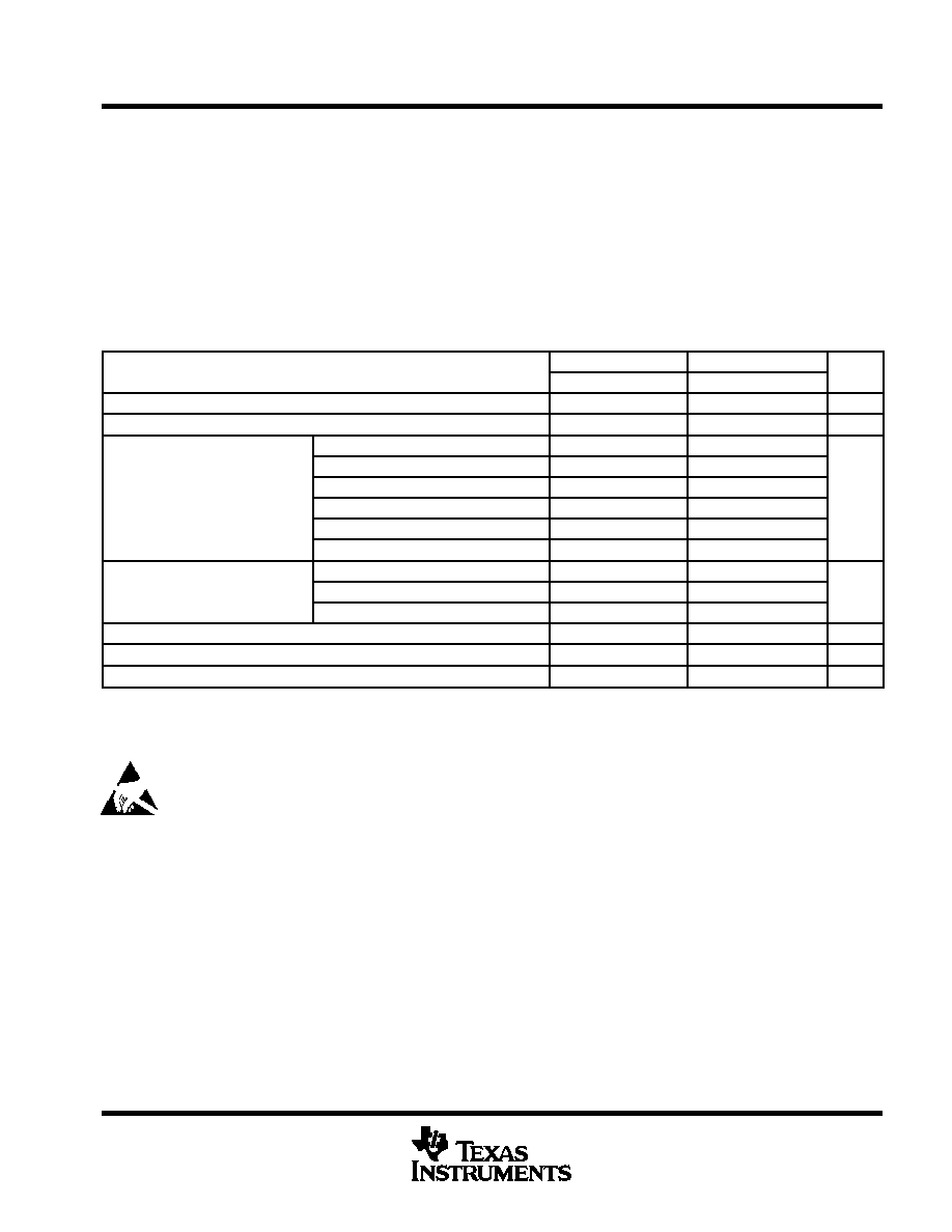
recommended operating conditions
SMJ320C25-50
SMJ320C25
UNIT
MIN
NOM
MAX
MIN
NOM
MAX
UNIT
VCC
Supply voltage
4.75
5
5.25
4.5
5
5.5
V
VSS
Supply voltage
0
V
READY
3.00
2.35
D15–D0
2.20
V
High le el inp t oltage
FSX
2.20
2.30
V
VIH
High-level input voltage
CLKR, CLKX
3.50
V
CLKIN
4.00
3.50
All others
3.00
D15–D0, FSX, CLKIN, CLKR, CLKX
0.80
VIL
Low-level input voltage
HOLD
0.70
V
VIL
Low level in ut voltage
All others
0.80
0.70
V
IOH
High-level output current
300
mA
IOL
Low-level output current
2
mA
TC
Operating case temperature
–55
125
–55
125
°C
TC MAX at maximum rated operating conditions at any point on case TC MIN at initial (time zero) power up
This device contains circuits to protect its inputs and outputs against damage due to high static voltages or electrostatic fields. These
circuits have been qualified to protect this device against electrostatic discharges (ESD) of up to 2 kV according to MIL-STD-883C,
Method 3015; however, it is advised that precautions be taken to avoid application of any voltage higher than maximum-rated
voltages to these high-impedance circuits. During storage or handling, the device leads should be shorted together or the device
should be placed in conductive foam. In a circuit, unused inputs should always be connected to an appropriated logic voltage level,
preferably either VCC or ground. Specific guidelines for handling devices of this type are contained in the publication Guidelines for
Handling Electrostatic-Discharge-Sensitive (ESDS) Devices and Assemblies available from Texas Instruments.
相关PDF资料 |
PDF描述 |
|---|---|
| SM320C2550GBM | 16-BIT, 50 MHz, OTHER DSP, CPGA68 |
| SM320C30HFGM50 | 32-BIT, 50 MHz, OTHER DSP, CQFP196 |
| SM320C31GFM27 | 32-BIT, 27 MHz, OTHER DSP, CPGA141 |
| SM320C30HUM25 | 32-BIT, 25 MHz, OTHER DSP, CQFP196 |
| SM320C30HTM28 | 32-BIT, 28 MHz, OTHER DSP, CQFP196 |
相关代理商/技术参数 |
参数描述 |
|---|---|
| SM320C25FJM | 制造商:未知厂家 制造商全称:未知厂家 功能描述:16-Bit Digital Signal Processor |
| SM320C25GBM | 制造商:未知厂家 制造商全称:未知厂家 功能描述:16-Bit Digital Signal Processor |
| SM320C26BFJM | 制造商:Texas Instruments 功能描述:DSP FIX PT 16BIT 40MHZ 10MIPS 68PIN JLCC - Rail/Tube |
| SM320C26BGBM | 制造商:TI 制造商全称:Texas Instruments 功能描述:DIGITAL SIGNAL PROCESSOR |
| SM320C2810-EP | 制造商:TI 制造商全称:Texas Instruments 功能描述:Digital Signal Processors |
发布紧急采购,3分钟左右您将得到回复。