- 您现在的位置:买卖IC网 > PDF目录98082 > SM320C30HFGM50 (TEXAS INSTRUMENTS INC) 32-BIT, 50 MHz, OTHER DSP, CQFP196 PDF资料下载
参数资料
| 型号: | SM320C30HFGM50 |
| 厂商: | TEXAS INSTRUMENTS INC |
| 元件分类: | 数字信号处理 |
| 英文描述: | 32-BIT, 50 MHz, OTHER DSP, CQFP196 |
| 封装: | NONCONDUCTIVE TIE BAR, CERAMIC, QFP-196 |
| 文件页数: | 4/48页 |
| 文件大小: | 874K |
| 代理商: | SM320C30HFGM50 |
第1页第2页第3页当前第4页第5页第6页第7页第8页第9页第10页第11页第12页第13页第14页第15页第16页第17页第18页第19页第20页第21页第22页第23页第24页第25页第26页第27页第28页第29页第30页第31页第32页第33页第34页第35页第36页第37页第38页第39页第40页第41页第42页第43页第44页第45页第46页第47页第48页
SMJ320C30
DIGITAL SIGNAL PROCESSOR
SGUS014H -- FEBRUARY 1991 -- REVISED JUNE 2004
12
POST OFFICE BOX 1443
HOUSTON, TEXAS 77251--1443
electrical characteristics over recommended ranges of supply voltage (unless otherwise noted)
(see Note 5)
PARAMETER
TEST CONDITIONS
MIN
TYP
MAX
UNIT
VOH
High-level output voltage
VDD =MIN, IOH =MAX
2.4
3
V
Low level output voltage
For XA12--XA0
VDD =MIN, IOL =MAX
0.6*
V
VOL
Low-level output voltage
All others
VDD =MIN, IOL =MAX
0.3
0.6
V
IZ
High-impedance current
VDD =MAX
± 20
μA
II
Input current
VI =VSS to VDD
± 10
μA
IIP
Input current
Inputs with internal pullups (see Note 7)
-- 600
20
μA
IIC
Input current (X2/CLKIN)
VI =VSS to VDD
± 50
μA
I
S ppl c rrent
VDD =MAX,TA =25°C,
200
600
mA
ICC
Supply current
VDD = MAX, TA = 25 C,
tc(CI) = MIN, See Note 8
200
600
mA
IDD
Supply current, standby; IDLE2, clock shut off
VDD =5V, TA =25°C
50
mA
Ci
Input capacitance
15*
pF
Co
Output capacitance
20*
pF
Cx
X2/CLKIN capacitance
25*
pF
For conditions shown as MIN/MAX, use the appropriate value specified in recommended operating conditions.
All typical values are at VDD =5V, TA =25°C.
* This parameter is not production tested.
NOTES: 5. All input and output voltage levels are TTL compatible.
7. Pins with internal pullup devices: INT0--INT3,MC/MP, RSV0--RSV10. Although RSV0--RSV10 have internal pullup devices,
external pullups should be used on each pin as identified in the pin function tables.
8. Actual operating current is less than this maximum value. This value was obtained under specially produced worst-case test
conditions, which are not sustained during normal device operation. These conditions consist of continuous parallel writes of a
checkerboard pattern to both primary and expansion buses at the maximum rate possible. See Calculation of TMS320C30 Power
Dissipation Application Report (literature number SPRA020).
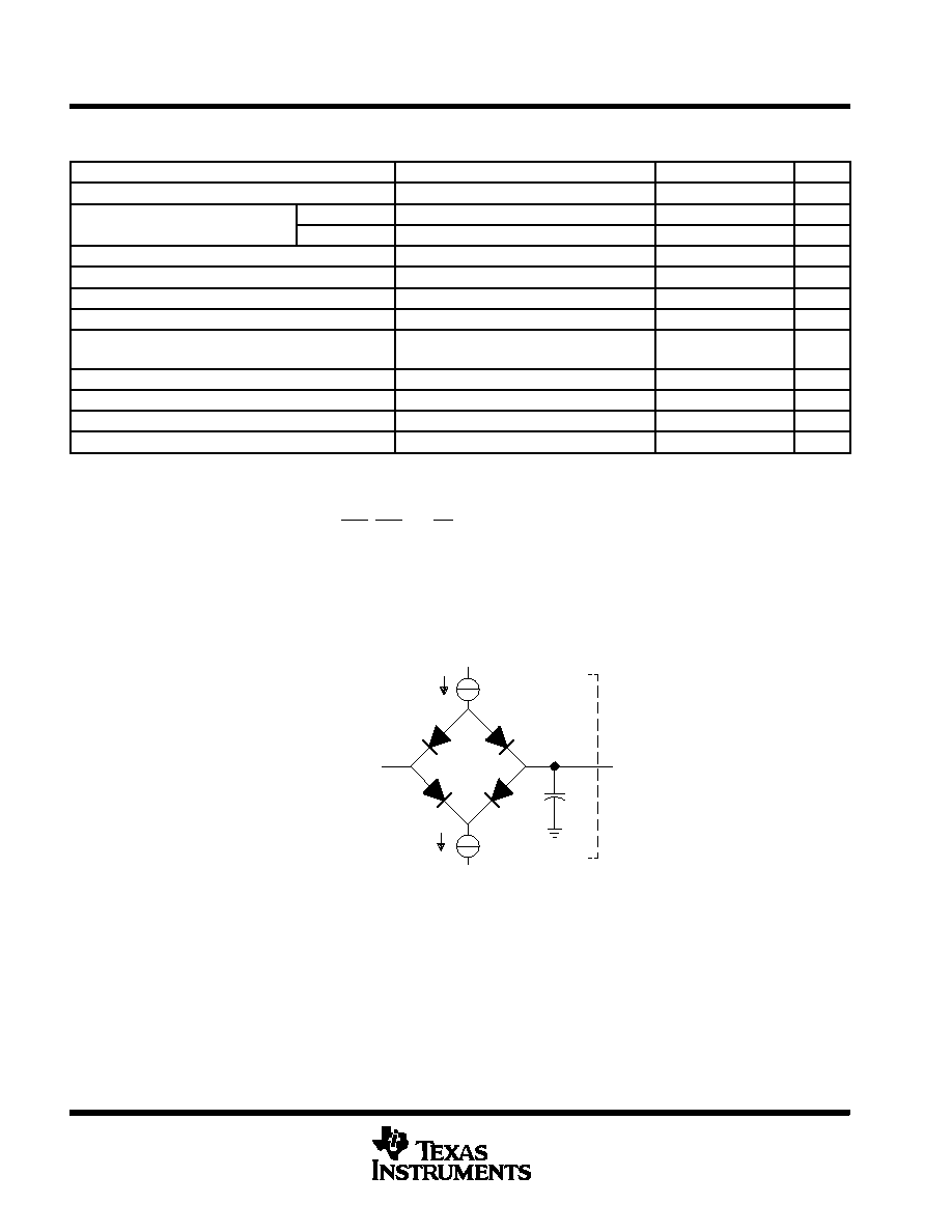
PARAMETER MEASUREMENT INFORMATION
Tester Pin
Electronics
VLOAD
IOL
CT
IOH
Output
Under
Test
Where:
IOL
= 2 mA (all outputs)
IOH
= 300 μA (all outputs)
VLOAD = Selected to emulate 50 termination (typical value = 1.54 V).
CT
= 80-pF typical load-circuit capacitance
Figure 4. Test Load Circuit
相关PDF资料 |
PDF描述 |
|---|---|
| SM320C31GFM27 | 32-BIT, 27 MHz, OTHER DSP, CPGA141 |
| SM320C30HUM25 | 32-BIT, 25 MHz, OTHER DSP, CQFP196 |
| SM320C30HTM28 | 32-BIT, 28 MHz, OTHER DSP, CQFP196 |
| SM320C30HFGM25 | 32-BIT, 25 MHz, OTHER DSP, CQFP196 |
| SM320C30HFGM28 | 32-BIT, 28 MHz, OTHER DSP, CQFP196 |
相关代理商/技术参数 |
参数描述 |
|---|---|
| SM320C31 WAF | 制造商:Texas Instruments 功能描述: |
| SM320C31GFAM40 | 制造商:TI 制造商全称:Texas Instruments 功能描述:DIGITAL SIGNAL PROCESSORS |
| SM320C31GFAM50 | 制造商:Rochester Electronics LLC 功能描述:- Bulk 制造商:Texas Instruments 功能描述:DSP FLOATING PT 32BIT 50MHZ 25MIPS 141CPGA - Trays |
| SM320C31GFAS60 | 制造商:Texas Instruments 功能描述:3RD GENERATION DSP, 60 MHZ - Trays |
| SM320C31HFGM40 | 制造商:Texas Instruments 功能描述:DSP FLOATING PT 32BIT 40MHZ 20MIPS 132CFPAK - Trays |
发布紧急采购,3分钟左右您将得到回复。