- 您现在的位置:买卖IC网 > PDF目录297474 > ST180C16C1LPBF (VISHAY INTERTECHNOLOGY INC) 660 A, 1600 V, SCR, TO-200AB PDF资料下载
参数资料
| 型号: | ST180C16C1LPBF |
| 厂商: | VISHAY INTERTECHNOLOGY INC |
| 元件分类: | 晶闸管 |
| 英文描述: | 660 A, 1600 V, SCR, TO-200AB |
| 封装: | LEAD FREE, APUK-2 |
| 文件页数: | 4/8页 |
| 文件大小: | 0K |
| 代理商: | ST180C16C1LPBF |
www.vishay.com
For technical questions, contact: ind-modules@vishay.com
Document Number: 94396
4
Revision: 11-Aug-08
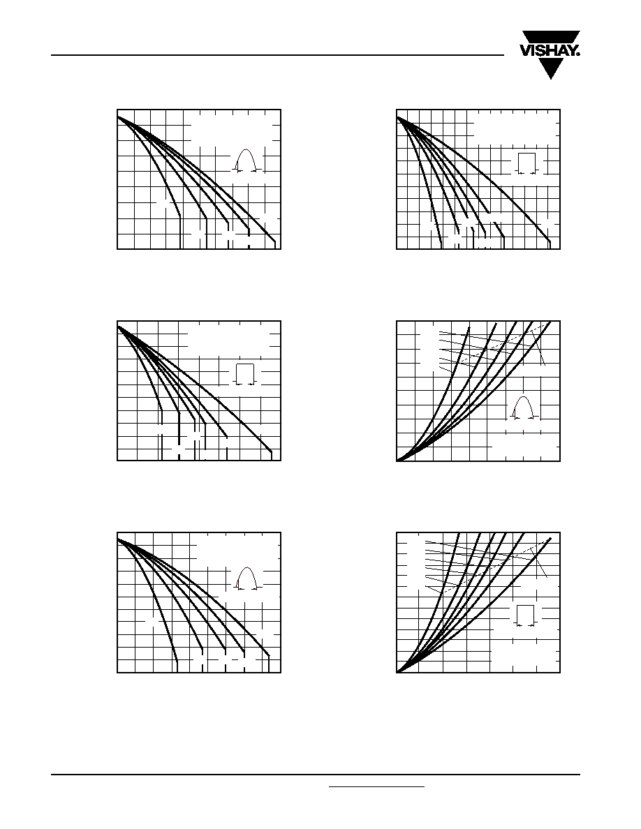
ST180CPbF Series
Vishay High Power Products
Phase Control Thyristors
(Hockey PUK Version), 350 A
Fig. 1 - Current Ratings Characteristics
Fig. 2 - Current Ratings Characteristics
Fig. 3 - Current Ratings Characteristics
Fig. 4 - Current Ratings Characteristics
Fig. 5 - On-State Power Loss Characteristics
Fig. 6 - On-State Power Loss Characteristics
110
100
50
60
70
80
90
40
130
0
Maxim
um
Allo
wab
le
Heatsink
T
e
mperature
(°C)
Average On-State Current (A)
50
120
100
150
200
250
ST180C..C Series
(Single side cooled)
R
thJ-hs (DC) = 0.17 K/W
Conduction angle
60°
30°
90°
120°
180°
0
200
400
Maxim
um
Allo
wab
le
Heatsink
T
e
mperature
(°C)
Average On-State Current (A)
300
100
110
100
40
50
60
70
80
90
20
130
120
30
ST180C..C Series
(Single side cooled)
R
thJ-hs (DC) = 0.17 K/W
30°
60°
90°
120°
180°
Conduction period
DC
0
Maxim
um
Allo
wab
le
Heatsink
T
e
mperature
(°C)
Average On-State Current (A)
50
100 150 200 250 300 350 400 450
Conduction angle
60°
30°
90°
120°
180°
ST180C..C Series
(Double side cooled)
R
thJ-hs (DC) = 0.17 K/W
110
100
40
50
60
70
80
90
20
130
120
30
0
200
400
500
600
700
Maxim
um
Allo
wab
le
Heatsink
T
e
mperature
(°C)
Average On-State Current (A)
300
100
110
100
40
50
60
70
80
90
20
130
120
30
ST180C..C Series
(Double side cooled)
R
thJ-hs (DC) = 0.08 K/W
30°
60°
90°
120°
180°
Conduction period
DC
700
600
100
200
300
400
500
0
900
1000
0
Maxim
um
A
vera
g
e
On-State
P
o
wer
Loss
(W)
Average On-State Current (A)
50
800
100 150 200 250 300 350 400 450
180°
120°
90°
60°
30°
RMS limit
Conduction angle
ST180C..C Series
T
J = 125 °C
700
600
100
200
300
400
500
0
900
1000
1100
1200
1300
0
Maxim
um
A
vera
g
e
On-State
P
o
wer
Loss
(W)
Average On-State Current (A)
800
100
200
300
400
500
600
700
DC
180°
120°
90°
60°
30°
RMS limit
ST180C..C Series
T
J = 125 °C
Conduction period
相关PDF资料 |
PDF描述 |
|---|---|
| ST180C16C1PBF | 660 A, 1600 V, SCR, TO-200AB |
| ST180C16C2LPBF | 660 A, 1600 V, SCR, TO-200AB |
| ST180C16C2PBF | 660 A, 1600 V, SCR, TO-200AB |
| ST180C16C3LPBF | 660 A, 1600 V, SCR, TO-200AB |
| ST180C16C3PBF | 660 A, 1600 V, SCR, TO-200AB |
相关代理商/技术参数 |
参数描述 |
|---|---|
| ST180C16C1PBF | 制造商:Vishay Intertechnologies 功能描述: |
| ST180C16C2 | 制造商:IRF 制造商全称:International Rectifier 功能描述:PHASE CONTROL THYRISTORS |
| ST180C16C2L | 制造商:IRF 制造商全称:International Rectifier 功能描述:PHASE CONTROL THYRISTORS |
| ST180C16C3 | 制造商:IRF 制造商全称:International Rectifier 功能描述:PHASE CONTROL THYRISTORS |
| ST180C16C3L | 制造商:IRF 制造商全称:International Rectifier 功能描述:PHASE CONTROL THYRISTORS |
发布紧急采购,3分钟左右您将得到回复。