- 您现在的位置:买卖IC网 > PDF目录69350 > ST62T00CM1 (STMICROELECTRONICS) 8-BIT, OTPROM, 8 MHz, MICROCONTROLLER, PDSO16 PDF资料下载
参数资料
| 型号: | ST62T00CM1 |
| 厂商: | STMICROELECTRONICS |
| 元件分类: | 微控制器/微处理器 |
| 英文描述: | 8-BIT, OTPROM, 8 MHz, MICROCONTROLLER, PDSO16 |
| 封装: | 0.300 INCH, PLASTIC, SOP-16 |
| 文件页数: | 10/100页 |
| 文件大小: | 1713K |
| 代理商: | ST62T00CM1 |
第1页第2页第3页第4页第5页第6页第7页第8页第9页当前第10页第11页第12页第13页第14页第15页第16页第17页第18页第19页第20页第21页第22页第23页第24页第25页第26页第27页第28页第29页第30页第31页第32页第33页第34页第35页第36页第37页第38页第39页第40页第41页第42页第43页第44页第45页第46页第47页第48页第49页第50页第51页第52页第53页第54页第55页第56页第57页第58页第59页第60页第61页第62页第63页第64页第65页第66页第67页第68页第69页第70页第71页第72页第73页第74页第75页第76页第77页第78页第79页第80页第81页第82页第83页第84页第85页第86页第87页第88页第89页第90页第91页第92页第93页第94页第95页第96页第97页第98页第99页第100页
ST6200C ST6201C ST6203C
17/100
CPU REGISTERS (Cont’d)
The 12-bit length allows the direct addressing of
4096 bytes in Program Space.
However, if the program space contains more than
4096 bytes, the additional memory in program
space can be addressed by using the Program
ROM Page register.
The PC value is incremented after reading the ad-
dress of the current instruction. To execute relative
jumps, the PC and the offset are shifted through
the ALU, where they are added; the result is then
shifted back into the PC. The program counter can
be changed in the following ways:
– JP (Jump) instruction
PC = Jump address
– CALL instruction
PC = Call address
– Relative Branch InstructionPC = PC +/- offset
– Interrupt
PC = Interrupt vector
– Reset
PC = Reset vector
– RET & RETI instructions
PC = Pop (stack)
– Normal instruction
PC = PC + 1
Flags (C, Z). The ST6 CPU includes three pairs of
flags (Carry and Zero), each pair being associated
with one of the three normal modes of operation:
Normal mode, Interrupt mode and Non Maskable
Interrupt mode. Each pair consists of a CARRY
flag and a ZERO flag. One pair (CN, ZN) is used
during Normal operation, another pair is used dur-
ing Interrupt mode (CI, ZI), and a third pair is used
in the Non Maskable Interrupt mode (CNMI, ZN-
MI).
The ST6 CPU uses the pair of flags associated
with the current mode: as soon as an interrupt (or
a Non Maskable Interrupt) is generated, the ST6
CPU uses the Interrupt flags (or the NMI flags) in-
stead of the Normal flags. When the RETI instruc-
tion is executed, the previously used set of flags is
restored. It should be noted that each flag set can
only be addressed in its own context (Non Maska-
ble Interrupt, Normal Interrupt or Main routine).
The flags are not cleared during context switching
and thus retain their status.
C : Carry flag.
This bit is set when a carry or a borrow occurs dur-
ing arithmetic operations; otherwise it is cleared.
The Carry flag is also set to the value of the bit
tested in a bit test instruction; it also participates in
the rotate left instruction.
0: No carry has occured
1: A carry has occured
Z : Zero flag
This flag is set if the result of the last arithmetic or
logical operation was equal to zero; otherwise it is
cleared.
0: The result of the last operation is different from
zero
1: The result of the last operation is zero
Switching between the three sets of flags is per-
formed automatically when an NMI, an interrupt or
a RETI instruction occurs. As NMI mode is auto-
matically selected after the reset of the MCU, the
ST6 core uses the NMI flags first.
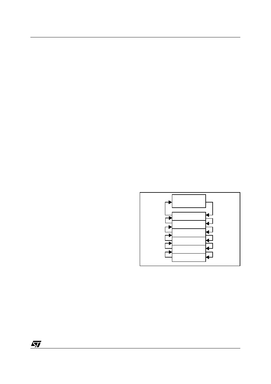
Stack. The ST6 CPU includes a true LIFO (Last In
First Out) hardware stack which eliminates the
need for a stack pointer. The stack consists of six
separate 12-bit RAM locations that do not belong
to the data space RAM area. When a subroutine
call (or interrupt request) occurs, the contents of
each level are shifted into the next level down,
while the content of the PC is shifted into the first
level (the original contents of the sixth stack level
are lost). When a subroutine or interrupt return oc-
curs (RET or RETI instructions), the first level reg-
ister is shifted back into the PC and the value of
each level is popped back into the previous level.
Figure 8. Stack manipulation
Since the accumulator, in common with all other
data space registers, is not stored in this stack,
management of these registers should be per-
formed within the subroutine.
Caution: The stack will remain in its “deepest” po-
sition if more than 6 nested calls or interrupts are
executed, and consequently the last return ad-
dress will be lost.
It will also remain in its highest position if the stack
is empty and a RET or RETI is executed. In this
case the next instruction will be executed.
LEVEL 1
LEVEL 2
LEVEL 3
LEVEL 4
LEVEL 5
LEVEL 6
ON
INTERRUPT,
OR
SUBROUTINE
CALL
ON RETURN
FROM
INTERRUPT,
OR
SUBROUTINE
PROGRAM
COUNTER
1
相关PDF资料 |
PDF描述 |
|---|---|
| ST62T00CN1 | 8-BIT, OTPROM, 8 MHz, MICROCONTROLLER, PDSO16 |
| ST62T00CN6 | 8-BIT, OTPROM, 8 MHz, MICROCONTROLLER, PDSO16 |
| ST62T01CB3 | 8-BIT, OTPROM, 8 MHz, MICROCONTROLLER, PDIP16 |
| ST62T01CN1 | 8-BIT, OTPROM, 8 MHz, MICROCONTROLLER, PDSO16 |
| ST62P03CB1/XXX | 8-BIT, MROM, 8 MHz, MICROCONTROLLER, PDIP16 |
相关代理商/技术参数 |
参数描述 |
|---|---|
| ST62T00CM6 | 功能描述:8位微控制器 -MCU OTP EPROM 1K No Intf RoHS:否 制造商:Silicon Labs 核心:8051 处理器系列:C8051F39x 数据总线宽度:8 bit 最大时钟频率:50 MHz 程序存储器大小:16 KB 数据 RAM 大小:1 KB 片上 ADC:Yes 工作电源电压:1.8 V to 3.6 V 工作温度范围:- 40 C to + 105 C 封装 / 箱体:QFN-20 安装风格:SMD/SMT |
| ST62T00CM6/TR | 功能描述:8位微控制器 -MCU 8B MCUS A/D CONVERTR TWO TIMER OSCILLATOR RoHS:否 制造商:Silicon Labs 核心:8051 处理器系列:C8051F39x 数据总线宽度:8 bit 最大时钟频率:50 MHz 程序存储器大小:16 KB 数据 RAM 大小:1 KB 片上 ADC:Yes 工作电源电压:1.8 V to 3.6 V 工作温度范围:- 40 C to + 105 C 封装 / 箱体:QFN-20 安装风格:SMD/SMT |
| ST62T01CB3 | 功能描述:8位微控制器 -MCU ST6200C ST6201C ST6203C 8B MCU RoHS:否 制造商:Silicon Labs 核心:8051 处理器系列:C8051F39x 数据总线宽度:8 bit 最大时钟频率:50 MHz 程序存储器大小:16 KB 数据 RAM 大小:1 KB 片上 ADC:Yes 工作电源电压:1.8 V to 3.6 V 工作温度范围:- 40 C to + 105 C 封装 / 箱体:QFN-20 安装风格:SMD/SMT |
| ST62T01CB6 | 功能描述:8位微控制器 -MCU OTP EPROM 2K No Intf RoHS:否 制造商:Silicon Labs 核心:8051 处理器系列:C8051F39x 数据总线宽度:8 bit 最大时钟频率:50 MHz 程序存储器大小:16 KB 数据 RAM 大小:1 KB 片上 ADC:Yes 工作电源电压:1.8 V to 3.6 V 工作温度范围:- 40 C to + 105 C 封装 / 箱体:QFN-20 安装风格:SMD/SMT |
| ST62T01CB6 | 制造商:STMicroelectronics 功能描述:IC 8BIT MCU OTP 2K 62T01 DIP16 |
发布紧急采购,3分钟左右您将得到回复。