- 您现在的位置:买卖IC网 > PDF目录385871 > ST70135A (意法半导体) ASCOTTM DMT TRANSCEIVER PDF资料下载
参数资料
| 型号: | ST70135A |
| 厂商: | 意法半导体 |
| 英文描述: | ASCOTTM DMT TRANSCEIVER |
| 中文描述: | ASCOTTM大唐收发器 |
| 文件页数: | 22/29页 |
| 文件大小: | 198K |
| 代理商: | ST70135A |
第1页第2页第3页第4页第5页第6页第7页第8页第9页第10页第11页第12页第13页第14页第15页第16页第17页第18页第19页第20页第21页当前第22页第23页第24页第25页第26页第27页第28页第29页
ST70135A
22/29
The implementation must guarantee that all active
SLR_Valid signals must be separated by at least 8
clock cycles. Refer to Figure 20. The SLR_FRAME
signals are asserted when the first pair of bits of a
frame are transferred. For the fast channel a frame
is defined as a superframe timebase.
For the interleaved channel the frame is defined
by a timebase period of 4 superframes. Both
timebases are synchronized to the data flow.
Transmit SLAP Interface
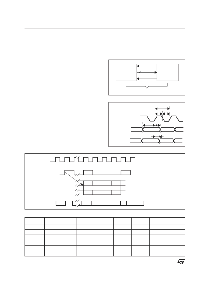
The Transmit interface uses the following signals
(refer to Figure 21):
– SLT_REQ: byte request.
– SLT_FRAME: start of frame indication.
– SLT_DATA [1:0] data pins, a byte is transferred
2 bits at the time in 4 successive clock cycles.
MSB first, odd bits on SLT_DATA [1].
The logical timing diagram is shown in Figure 22.
The delay between Request and the associated
data byte is defined as 8 cycles.
The SLT_FRAME signals are asserted when the
first pair of bits of a frame are transferred. For the
fast channel a frame is defined as a superframe
timebase.
For the interleaved channel the frame is defined
by a timebase period of 4 superframes.
Figure 23 :
Transmit SLAP Interface Timing Diagram
Both timebases are synchronized to the data flow
and guarantee that the frame indication is
asserted when the first bits of the first DMT
symbol are transferred.
Figure 21 :
Interface Towards PHY Layer
SLAP INTERFACE, AC Electrical Characteristics
Figure 22 :
Interface Timing
EXTERNAL
COMPONENT
(SLAVE)
CLOCK
MODEM
(MASTER)
REQUEST
2DATA
FRAME
T
per
T
h
T
l
T
hd
T
s
T
d
CLOCK
ALLINPUTS
ALL OUTPUTS
Symbol
Parameter
Test Condition
Minimum
Typical
Maximum
Unit
T
per
T
h
T
l
T
s
T
hd
T
d
Clock Period
Refer to MCLK
ns
Clock High
11
ns
Clock Low
11
ns
Setup
3
ns
Hold
2
ns
Data Delay
20pF load
3
6
ns
Onebytein 4cycles
b4
b6
0
1
8
9
1
CLOCK
Undefined
Undefined
Request maybe repeated
after4 cycles
Delay Request-data equals 8 cycles
b5
b3
b1
b2
b0
b7
SLT_DATA(0)
SLT_FRAME
1
0
1
2
Repeated each superframe/
S-frame
STM_CLOCK
SLT_DATA(1)
SLT_REQUEST
相关PDF资料 |
PDF描述 |
|---|---|
| ST70136 | CPE ADSL ANALOG FRONT END |
| ST70136B | CPE ADSL ANALOG FRONT END |
| ST70136G | CPE ADSL ANALOG FRONT END |
| ST70137 | UNICORNTM PCI & USB CONTROLLERLESS ADSL DMT TRANSCEIVER |
| ST70137TQFP | UNICORNTM PCI & USB CONTROLLERLESS ADSL DMT TRANSCEIVER |
相关代理商/技术参数 |
参数描述 |
|---|---|
| ST70136 | 制造商:STMICROELECTRONICS 制造商全称:STMicroelectronics 功能描述:CPE ADSL ANALOG FRONT END |
| ST70136B | 制造商:STMICROELECTRONICS 制造商全称:STMicroelectronics 功能描述:CPE ADSL ANALOG FRONT END |
| ST70136G | 制造商:STMICROELECTRONICS 制造商全称:STMicroelectronics 功能描述:CPE ADSL ANALOG FRONT END |
| ST70136Q | 功能描述:射频无线杂项 ADSL Analg Front-End RoHS:否 制造商:Texas Instruments 工作频率:112 kHz to 205 kHz 电源电压-最大:3.6 V 电源电压-最小:3 V 电源电流:8 mA 最大功率耗散: 工作温度范围:- 40 C to + 110 C 封装 / 箱体:VQFN-48 封装:Reel |
| ST70137 | 制造商:STMicroelectronics 功能描述: |
发布紧急采购,3分钟左右您将得到回复。