- 您现在的位置:买卖IC网 > PDF目录98144 > ST72311N2T3/XXX (STMICROELECTRONICS) 8-BIT, MROM, 8 MHz, MICROCONTROLLER, PQFP64 PDF资料下载
参数资料
| 型号: | ST72311N2T3/XXX |
| 厂商: | STMICROELECTRONICS |
| 元件分类: | 微控制器/微处理器 |
| 英文描述: | 8-BIT, MROM, 8 MHz, MICROCONTROLLER, PQFP64 |
| 封装: | PLASTIC, TQFP-64 |
| 文件页数: | 37/92页 |
| 文件大小: | 624K |
| 代理商: | ST72311N2T3/XXX |
第1页第2页第3页第4页第5页第6页第7页第8页第9页第10页第11页第12页第13页第14页第15页第16页第17页第18页第19页第20页第21页第22页第23页第24页第25页第26页第27页第28页第29页第30页第31页第32页第33页第34页第35页第36页当前第37页第38页第39页第40页第41页第42页第43页第44页第45页第46页第47页第48页第49页第50页第51页第52页第53页第54页第55页第56页第57页第58页第59页第60页第61页第62页第63页第64页第65页第66页第67页第68页第69页第70页第71页第72页第73页第74页第75页第76页第77页第78页第79页第80页第81页第82页第83页第84页第85页第86页第87页第88页第89页第90页第91页第92页
42/92
ST72311
16-BIT TIMER (Cont’d)
4.3.3.7 Pulse Width Modulation Mode
Pulse Width Modulation mode enables the gener-
ation of a signal with a frequency and pulse length
determined by the value of the OC1R and OC2R
registers.
The pulse width modulation mode uses the com-
plete Output Compare 1 function plus the OC2R
register.
Procedure
To use pulse width modulation mode:
1. Load the OC2R register with the value corre-
sponding to the period of the signal.
2. Load the OC1R register with the value corre-
sponding to the length of the pulse if (OLVL1=0
and OLVL2=1).
3. Select the following in the CR1 register:
– Using the OLVL1 bit, select the level to be ap-
plied to the OCMP1 pin after a successful
comparison with OC1R register.
– Using the OLVL2 bit, select the level to be ap-
plied to the OCMP1 pin after a successful
comparison with OC2R register.
4. Select the following in the CR2 register:
– Set OC1E bit: the OCMP1 pin is then dedicat-
ed to the output compare 1 function.
– Set the PWM bit.
– Select the timer clock (CC1-CC0) (see Table
15).
If OLVL1=1 and OLVL2=0 the length of the pulse
is the difference between the OC2R and OC1R
registers.
The OCiR register value required for a specific tim-
ing application can be calculated using the follow-
ing formula:
Where:
– t = Desired output compare period (seconds)
–fCPU = Internal clock frequency (see Miscella-
neous register)
–
tPRESC = Timer clock prescaler (CC1-CC0
bits , see Table 15)
The Output Compare 2 event causes the counter
to be initialized to FFFCh (See Figure 32).
Note: After a write instruction to the OC
iHR regis-
ter, the output compare function is inhibited until
the OC
iLR register is also written.
The ICF1 bit is set by hardware when the counter
reaches the OC2R value and can produce a timer
interrupt if the ICIE bit is set and the I bit is cleared.
Therefore the Input Capture 1 function is inhibited
but the Input Capture 2 is available.
The OCF1 and OCF2 bits cannot be set by hard-
ware in PWM mode therefore the Output Compare
interrupt is inhibited.
When the Pulse Width Modulation (PWM) and
One Pulse Mode (OPM) bits are both set, the
PWM mode is the only active one.
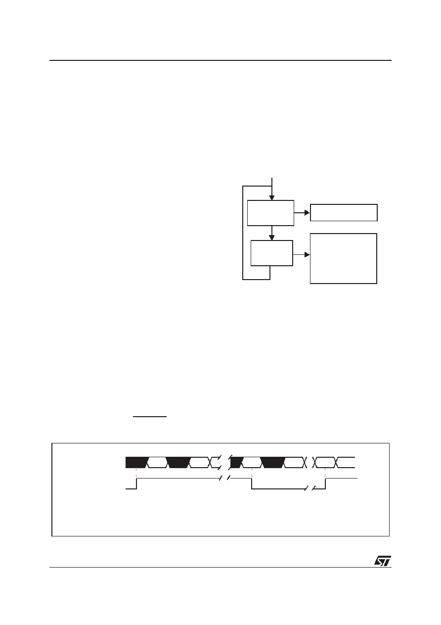
Figure 32. Pulse Width Modulation Mode Timing
OC
iR Value =
t * fCPU
tPRESC
-5
Counter
OCMP1 = OLVL2
Counter
= OC2R
OCMP1 = OLVL1
When
= OC1R
Pulse Width Modulation cycle
Counter is reset
to FFFCh
ICF1 bit is set
COUNTER
34E2
FFF C FFF D FFFE
2ED0 2ED1 2ED2
34E2
FFFC
OLVL2
OLVL1
OCMP1
compare2
compare1
compare2
Note: OC1R=2ED0h, OC2R=34E2, OLVL1=0, OLVL2= 1
42
相关PDF资料 |
PDF描述 |
|---|---|
| ST72321BAR7T6 | MICROCONTROLLER, QFP64 |
| ST72321BR7T3 | MICROCONTROLLER, QFP64 |
| ST72321M9T3/XXX | 8-BIT, MROM, MICROCONTROLLER, PQFP80 |
| ST72321M7T5/XXX | 8-BIT, MROM, MICROCONTROLLER, PQFP80 |
| ST72321M7T7/XXX | 8-BIT, MROM, MICROCONTROLLER, PQFP80 |
相关代理商/技术参数 |
参数描述 |
|---|---|
| ST72311N2T6 | 制造商:STMICROELECTRONICS 制造商全称:STMicroelectronics 功能描述:8-BIT MCU WITH 8 TO 16K ROM/OTP/EPROM, 384 TO 512 BYTES RAM, ADC, WDG, SCI, SPI AND 2 TIMERS |
| ST72311N2T6/XXX | 制造商:未知厂家 制造商全称:未知厂家 功能描述:8-Bit Microcontroller |
| ST72311N2T6S | 制造商:STMICROELECTRONICS 制造商全称:STMicroelectronics 功能描述:8-BIT MCU WITH 8 TO 16K ROM/OTP/EPROM, 384 TO 512 BYTES RAM, ADC, WDG, SCI, SPI AND 2 TIMERS |
| ST72311N4 | 制造商:STMICROELECTRONICS 制造商全称:STMicroelectronics 功能描述:8-BIT MCU WITH 8 TO 16K ROM/OTP/EPROM, 384 TO 512 BYTES RAM, ADC, WDG, SCI, SPI AND 2 TIMERS |
| ST72311N4B1 | 制造商:STMICROELECTRONICS 制造商全称:STMicroelectronics 功能描述:8-BIT MCU WITH 8 TO 16K ROM/OTP/EPROM, 384 TO 512 BYTES RAM, ADC, WDG, SCI, SPI AND 2 TIMERS |
发布紧急采购,3分钟左右您将得到回复。