- 您现在的位置:买卖IC网 > PDF目录98145 > ST72621J2B1 (STMICROELECTRONICS) 8-BIT, MROM, 8 MHz, MICROCONTROLLER, PDIP20 PDF资料下载
参数资料
| 型号: | ST72621J2B1 |
| 厂商: | STMICROELECTRONICS |
| 元件分类: | 微控制器/微处理器 |
| 英文描述: | 8-BIT, MROM, 8 MHz, MICROCONTROLLER, PDIP20 |
| 封装: | 0.300 INCH, PLASTIC, DIP-20 |
| 文件页数: | 59/136页 |
| 文件大小: | 2475K |
| 代理商: | ST72621J2B1 |
第1页第2页第3页第4页第5页第6页第7页第8页第9页第10页第11页第12页第13页第14页第15页第16页第17页第18页第19页第20页第21页第22页第23页第24页第25页第26页第27页第28页第29页第30页第31页第32页第33页第34页第35页第36页第37页第38页第39页第40页第41页第42页第43页第44页第45页第46页第47页第48页第49页第50页第51页第52页第53页第54页第55页第56页第57页第58页当前第59页第60页第61页第62页第63页第64页第65页第66页第67页第68页第69页第70页第71页第72页第73页第74页第75页第76页第77页第78页第79页第80页第81页第82页第83页第84页第85页第86页第87页第88页第89页第90页第91页第92页第93页第94页第95页第96页第97页第98页第99页第100页第101页第102页第103页第104页第105页第106页第107页第108页第109页第110页第111页第112页第113页第114页第115页第116页第117页第118页第119页第120页第121页第122页第123页第124页第125页第126页第127页第128页第129页第130页第131页第132页第133页第134页第135页第136页
ST7262
29/136
8 POWER SAVING MODES
8.1 INTRODUCTION
There are three Power Saving modes. Slow Mode
is selected by setting the SMS bits in the Miscella-
neous register. Wait and Halt modes may be en-
tered using the WFI and HALT instructions.
After a RESET the normal operating mode is se-
lected by default (RUN mode). This mode drives
the device (CPU and embedded peripherals) by
means of a master clock which is based on the
main oscillator frequency divided by 3 and multi-
plied by 2 (fCPU).
From Run mode, the different power saving
modes may be selected by setting the relevant
register bits or by calling the specific ST7 software
instruction whose action depends on the oscillator
status.
8.1.1 Slow Mode
In Slow mode, the oscillator frequency can be di-
vided by a value defined in the Miscellaneous
Register. The CPU and peripherals are clocked at
this lower frequency. Slow mode is used to reduce
power consumption, and enables the user to adapt
clock frequency to available supply voltage.
8.2 WAIT MODE
WAIT mode places the MCU in a low power con-
sumption mode by stopping the CPU.
This power saving mode is selected by calling the
“WFI” ST7 software instruction.
All peripherals remain active. During WAIT mode,
the I bit of the CC register is forced to 0, to enable
all interrupts. All other registers and memory re-
main unchanged. The MCU remains in WAIT
mode until an interrupt or Reset occurs, whereup-
on the Program Counter branches to the starting
address of the interrupt or Reset service routine.
The MCU will remain in WAIT mode until a Reset
or an Interrupt occurs, causing it to wake up.
Refer to Figure 24.
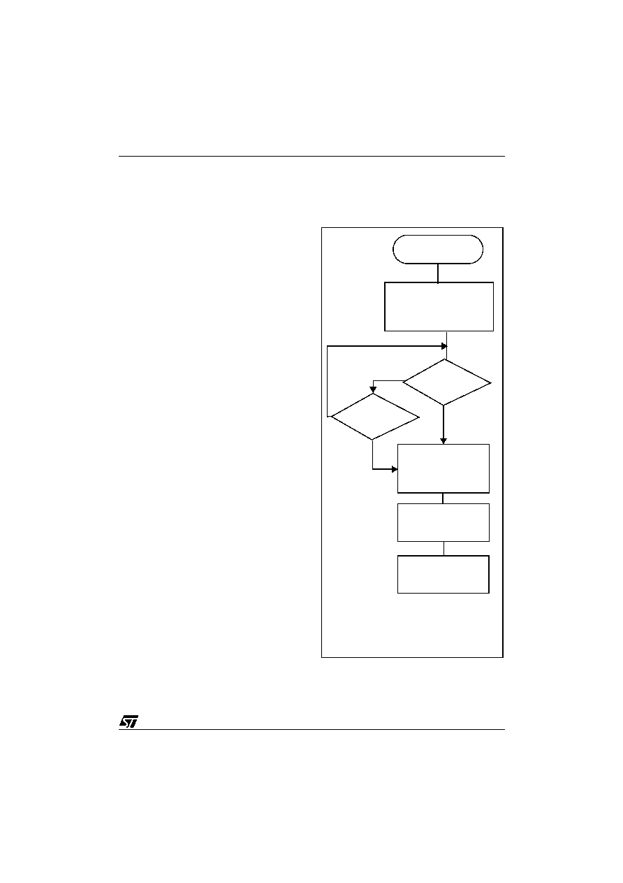
Figure 24. WAIT Mode Flow Chart
WFI INSTRUCTION
RESET
INTERRUPT
Y
N
Y
CPU CLOCK
OSCILLATOR
PERIPH. CLOCK
I-BIT
ON
CLEARED
OFF
CPU CLOCK
OSCILLATOR
PERIPH. CLOCK
I-BIT
ON
SET
ON
FETCH RESET VECTOR
OR SERVICE INTERRUPT
514 CPU CLOCK
CYCLES DELAY
IF RESET
Note: Before servicing an interrupt, the CC register is
pushed on the stack. The I-Bit is set during the inter-
rupt routine and cleared when the CC register is
popped.
相关PDF资料 |
PDF描述 |
|---|---|
| ST72621J2T1 | 8-BIT, MROM, 8 MHz, MICROCONTROLLER, PDSO20 |
| ST72P621L4M1 | 8-BIT, MROM, 8 MHz, MICROCONTROLLER, PDSO34 |
| ST72623F2M1L | 8-BIT, MROM, 4 MHz, MICROCONTROLLER, PDSO34 |
| ST7263BK1B/XXX | 8-BIT, MROM, 8 MHz, MICROCONTROLLER, PDIP32 |
| ST72652AR4T1/XXX | 8-BIT, MROM, MICROCONTROLLER, PQFP64 |
相关代理商/技术参数 |
参数描述 |
|---|---|
| ST7263-EMU2 | 功能描述:仿真器/模拟器 ST7 Emulator Board RoHS:否 制造商:Blackhawk 产品:System Trace Emulators 工具用于评估:C6000, C5000, C2000, OMAP, DAVINCI, SITARA, TMS470, TMS570, ARM 7/9, ARM Cortex A8/R4/M3 用于:XDS560v2 |
| ST7265X-EVAL/MS | 制造商:STMicroelectronics 功能描述:ST6 EVAL BD - Bulk |
| ST7265X-EVAL/PFD | 制造商:STMicroelectronics 功能描述:USB FLASH EVAL - Bulk |
| ST7266 | 制造商:6940 功能描述:ST7266 |
| ST7267C8T1L | 制造商:STMicroelectronics 功能描述: |
发布紧急采购,3分钟左右您将得到回复。