- 您现在的位置:买卖IC网 > PDF目录98145 > ST72P621J4T1 (STMICROELECTRONICS) 8-BIT, MROM, 8 MHz, MICROCONTROLLER, PDSO34 PDF资料下载
参数资料
| 型号: | ST72P621J4T1 |
| 厂商: | STMICROELECTRONICS |
| 元件分类: | 微控制器/微处理器 |
| 英文描述: | 8-BIT, MROM, 8 MHz, MICROCONTROLLER, PDSO34 |
| 封装: | PLASTIC, SO-34 |
| 文件页数: | 75/136页 |
| 文件大小: | 2475K |
| 代理商: | ST72P621J4T1 |
第1页第2页第3页第4页第5页第6页第7页第8页第9页第10页第11页第12页第13页第14页第15页第16页第17页第18页第19页第20页第21页第22页第23页第24页第25页第26页第27页第28页第29页第30页第31页第32页第33页第34页第35页第36页第37页第38页第39页第40页第41页第42页第43页第44页第45页第46页第47页第48页第49页第50页第51页第52页第53页第54页第55页第56页第57页第58页第59页第60页第61页第62页第63页第64页第65页第66页第67页第68页第69页第70页第71页第72页第73页第74页当前第75页第76页第77页第78页第79页第80页第81页第82页第83页第84页第85页第86页第87页第88页第89页第90页第91页第92页第93页第94页第95页第96页第97页第98页第99页第100页第101页第102页第103页第104页第105页第106页第107页第108页第109页第110页第111页第112页第113页第114页第115页第116页第117页第118页第119页第120页第121页第122页第123页第124页第125页第126页第127页第128页第129页第130页第131页第132页第133页第134页第135页第136页
ST7262
43/136
PWM AUTO-RELOAD TIMER (Cont’d)
10.2.2 Functional Description
Counter
The free running 8-bit counter is fed by the output
of the prescaler, and is incremented on every ris-
ing edge of the clock signal.
It is possible to read or write the contents of the
counter on the fly by reading or writing the Counter
Access register (ARTCAR).
When a counter overflow occurs, the counter is
automatically reloaded with the contents of the
ARTARR register (the prescaler is not affected).
Counter clock and prescaler
The counter clock frequency is given by:
fCOUNTER = fINPUT / 2
CC[2:0]
The timer counter’s input clock (fINPUT) feeds the
7-bit programmable prescaler, which selects one
of the 8 available taps of the prescaler, as defined
by CC[2:0] bits in the Control/Status Register
(ARTCSR). Thus the division factor of the prescal-
er can be set to 2n (where n = 0, 1,..7).
This fINPUT frequency source is selected through
the EXCL bit of the ARTCSR register and can be
either the fCPU or an external input frequency fEXT.
The clock input to the counter is enabled by the
TCE (Timer Counter Enable) bit in the ARTCSR
register. When TCE is reset, the counter is
stopped and the prescaler and counter contents
are frozen. When TCE is set, the counter runs at
the rate of the selected clock source.
Counter and Prescaler Initialization
After RESET, the counter and the prescaler are
cleared and fINPUT = fCPU.
The counter can be initialized by:
– Writing to the ARTARR register and then setting
the FCRL (Force Counter Re-Load) and the TCE
(Timer Counter Enable) bits in the ARTCSR reg-
ister.
– Writing to the ARTCAR counter access register,
In both cases the 7-bit prescaler is also cleared,
whereupon counting will start from a known value.
Direct access to the prescaler is not possible.
Output compare control
The timer compare function is based on four differ-
ent comparisons with the counter (one for each
PWMx output). Each comparison is made be-
tween the counter value and an output compare
register (OCRx) value. This OCRx register can not
be accessed directly, it is loaded from the duty cy-
cle register (PWMDCRx) at each overflow of the
counter.
This double buffering method avoids glitch gener-
ation when changing the duty cycle on the fly.
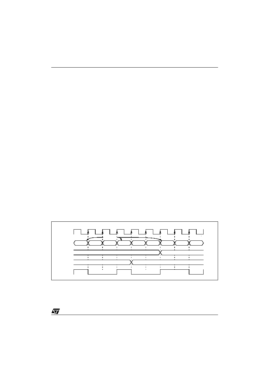
Figure 32. Output compare control
COUNTER
FDh
FEh
FFh
FDh
FEh
FFh
FDh
FEh
ARTARR=FDh
fCOUNTER
OCRx
PWMDCRx
FDh
FEh
FDh
FEh
FFh
PWMx
相关PDF资料 |
PDF描述 |
|---|---|
| ST72621J2B1 | 8-BIT, MROM, 8 MHz, MICROCONTROLLER, PDIP20 |
| ST72621J2T1 | 8-BIT, MROM, 8 MHz, MICROCONTROLLER, PDSO20 |
| ST72P621L4M1 | 8-BIT, MROM, 8 MHz, MICROCONTROLLER, PDSO34 |
| ST72623F2M1L | 8-BIT, MROM, 4 MHz, MICROCONTROLLER, PDSO34 |
| ST7263BK1B/XXX | 8-BIT, MROM, 8 MHz, MICROCONTROLLER, PDIP32 |
相关代理商/技术参数 |
参数描述 |
|---|---|
| ST72T101G1B6 | 功能描述:8位微控制器 -MCU OTP EPROM 4K SPI RoHS:否 制造商:Silicon Labs 核心:8051 处理器系列:C8051F39x 数据总线宽度:8 bit 最大时钟频率:50 MHz 程序存储器大小:16 KB 数据 RAM 大小:1 KB 片上 ADC:Yes 工作电源电压:1.8 V to 3.6 V 工作温度范围:- 40 C to + 105 C 封装 / 箱体:QFN-20 安装风格:SMD/SMT |
| ST72T101G1M6 | 功能描述:8位微控制器 -MCU OTP EPROM 4K SPI RoHS:否 制造商:Silicon Labs 核心:8051 处理器系列:C8051F39x 数据总线宽度:8 bit 最大时钟频率:50 MHz 程序存储器大小:16 KB 数据 RAM 大小:1 KB 片上 ADC:Yes 工作电源电压:1.8 V to 3.6 V 工作温度范围:- 40 C to + 105 C 封装 / 箱体:QFN-20 安装风格:SMD/SMT |
| ST72T101G2B6 | 功能描述:8位微控制器 -MCU OTP EPROM 8K SPI RoHS:否 制造商:Silicon Labs 核心:8051 处理器系列:C8051F39x 数据总线宽度:8 bit 最大时钟频率:50 MHz 程序存储器大小:16 KB 数据 RAM 大小:1 KB 片上 ADC:Yes 工作电源电压:1.8 V to 3.6 V 工作温度范围:- 40 C to + 105 C 封装 / 箱体:QFN-20 安装风格:SMD/SMT |
| ST72T101G2M6 | 功能描述:8位微控制器 -MCU RO 511-ST72C104G2M6 RoHS:否 制造商:Silicon Labs 核心:8051 处理器系列:C8051F39x 数据总线宽度:8 bit 最大时钟频率:50 MHz 程序存储器大小:16 KB 数据 RAM 大小:1 KB 片上 ADC:Yes 工作电源电压:1.8 V to 3.6 V 工作温度范围:- 40 C to + 105 C 封装 / 箱体:QFN-20 安装风格:SMD/SMT |
| ST72T121J2B6 | 功能描述:8位微控制器 -MCU OTP EPROM 8K SPI/SCI RoHS:否 制造商:Silicon Labs 核心:8051 处理器系列:C8051F39x 数据总线宽度:8 bit 最大时钟频率:50 MHz 程序存储器大小:16 KB 数据 RAM 大小:1 KB 片上 ADC:Yes 工作电源电压:1.8 V to 3.6 V 工作温度范围:- 40 C to + 105 C 封装 / 箱体:QFN-20 安装风格:SMD/SMT |
发布紧急采购,3分钟左右您将得到回复。