- 您现在的位置:买卖IC网 > PDF目录69373 > ST72T671N4B1XXX (STMICROELECTRONICS) 8-BIT, OTPROM, 8 MHz, MICROCONTROLLER, PDIP56 PDF资料下载
参数资料
| 型号: | ST72T671N4B1XXX |
| 厂商: | STMICROELECTRONICS |
| 元件分类: | 微控制器/微处理器 |
| 英文描述: | 8-BIT, OTPROM, 8 MHz, MICROCONTROLLER, PDIP56 |
| 封装: | 0.600 INCH, SHRINK, PLASTIC, DIP-56 |
| 文件页数: | 17/101页 |
| 文件大小: | 608K |
| 代理商: | ST72T671N4B1XXX |
第1页第2页第3页第4页第5页第6页第7页第8页第9页第10页第11页第12页第13页第14页第15页第16页当前第17页第18页第19页第20页第21页第22页第23页第24页第25页第26页第27页第28页第29页第30页第31页第32页第33页第34页第35页第36页第37页第38页第39页第40页第41页第42页第43页第44页第45页第46页第47页第48页第49页第50页第51页第52页第53页第54页第55页第56页第57页第58页第59页第60页第61页第62页第63页第64页第65页第66页第67页第68页第69页第70页第71页第72页第73页第74页第75页第76页第77页第78页第79页第80页第81页第82页第83页第84页第85页第86页第87页第88页第89页第90页第91页第92页第93页第94页第95页第96页第97页第98页第99页第100页第101页
22/101
ST72671
3.4.5 Register Description
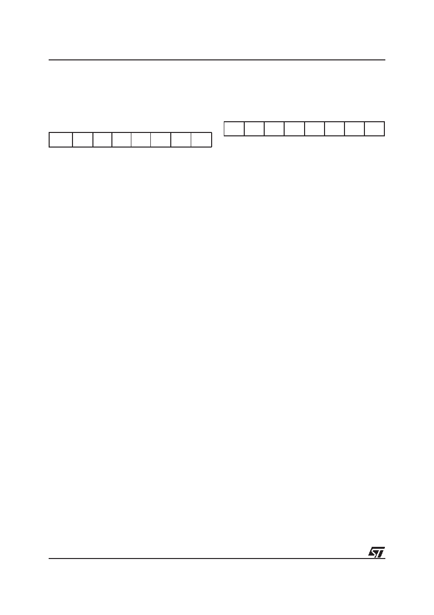
MISCELLANEOUS REGISTER (MISCR)
Read/Write
Reset Value: 0000 0000 (00h)
Bit 7 = EI4F
Falling Edge Detector Flag.
This bit is set by hardware when a falling edge oc-
curs on the pin assigned to EI4. An interrupt is
generated if EI4ITE=1 It is cleared by software.
0: No falling edge detected on EI4
1: Falling edge detected on EI4
Bit 6 = EI4ITE EI4 Interrupt Enable.
This bit is set and cleared by software.
0: EI4 interrupt disabled
1: EI4 interrupt enabled
Bit 5 = SMS
Slow Mode Select.
This bit is set and cleared by software. It is used to
select the slow or fast mode CPU frequency.
0: fCPU = Oscillator frequency / 6 (slow mode)
1: fCPU = Oscillator frequency / 3 (normal mode)
Bit 4: 1 = Reserved
Bit 0 = POC0 PWM/BRM Output Configuration Bit.
This bits is set and cleared by software. They se-
lect the PWM/BRM output configuration for pins
DA1-DA4.
0: Push-pull
1: Open drain
Note.
DA0 is only Push-Pull Output.
INTERRUPT REGISTER (ITRFRE)
Read/Write
Reset Value: 0000 0000 (00h)
Bit 7:5 = EI0F, EI1F, EI2F
Falling Edge Detector
Flags.
These bits are set by hardware when a falling
edge occurs on the pins assigned to EI0, EI1 or
EI2. They are cleared by software. When any of
these bits are set, an interrupt is generated if the
corresponding ITE bit =1 and the I bit in the CC
register = 0.
0: No falling edge detected
1: Falling edge detected
Bit 4 = EI3F
Rising Edge Detector Flag.
This bit is set by hardware when a rising edge oc-
curs on the pin assigned to EI3. It is cleared by
software. When EI3F is set an interrupt is generat-
ed if EI3ITE=1 and the I bit in the CC register = 0.
0: No rising edge detected on EI3
1: Rising edge detected on EI3
Bit 3:0 = EI0ITE, EI1ITE, EI2ITE, EI3ITE
Interrupt
Enable Bits.
These bits are set and cleared by software.
0: Interrupt disabled
1: Interrupt enabled
70
EI4F
EI4ITE
SMS
-
POC0
70
EI0F
EI1F
EI2F
EI3F
EI0ITE
EI1ITE
EI2ITE
EI3ITE
相关PDF资料 |
PDF描述 |
|---|---|
| ST72671N4B1/XXX | 8-BIT, MROM, 8 MHz, MICROCONTROLLER, PDIP56 |
| ST7FL19F1MATRE | 8-BIT, FLASH, 8 MHz, MICROCONTROLLER, PDSO20 |
| ST7FL34F2MCE | 8-BIT, FLASH, 8 MHz, MICROCONTROLLER, PDSO20 |
| ST7FL38F2MAE | 8-BIT, FLASH, 8 MHz, MICROCONTROLLER, PDSO20 |
| ST7FL35F2UCRE | 8-BIT, FLASH, 8 MHz, MICROCONTROLLER, QCC20 |
相关代理商/技术参数 |
参数描述 |
|---|---|
| ST72T754J9B1 | 制造商:STMicroelectronics 功能描述: |
| ST72T774J9B1 | 制造商:STMicroelectronics 功能描述: |
| ST72T774S9T1 | 制造商:STMicroelectronics 功能描述:ST72T774S9T1 - Trays |
| ST730 | 制造商:IRF 制造商全称:International Rectifier 功能描述:PHASE CONTROL THYRISTORS Hockey Puk Version |
| ST7-30 | 制造商:SUPERWORLD 制造商全称:Superworld Electronics 功能描述:POWER TRANSFORMER |
发布紧急采购,3分钟左右您将得到回复。