参数资料
| 型号: | ST78C36CJ44TR-F |
| 厂商: | Exar Corporation |
| 文件页数: | 5/27页 |
| 文件大小: | 0K |
| 描述: | IC UART FIFO 16B 44PLCC |
| 标准包装: | 500 |
| 特点: | * |
| FIFO's: | 16 字节 |
| 规程: | 打印机 |
| 电源电压: | 5V |
| 带并行端口: | 是 |
| 安装类型: | 表面贴装 |
| 封装/外壳: | 44-LCC(J 形引线) |
| 供应商设备封装: | 44-PLCC(16.59x16.59) |
| 包装: | 带卷 (TR) |
第1页第2页第3页第4页当前第5页第6页第7页第8页第9页第10页第11页第12页第13页第14页第15页第16页第17页第18页第19页第20页第21页第22页第23页第24页第25页第26页第27页
ST78C36/36A
13
REV. 5.1.0
ECP/EPP PARALLEL PRINTER PORT WITH 16-BYTE FIFO
4.7.2
DMA
DMA cycles occur only between the host and the FIFO data port (address 400) for PPF, ECP, or TST modes.
The selected DRQ(1, 2, or 3) will be driven high if ECR bit 3 (DMA) is high and ECR bit 2 (SI) is low when
{PDIR = 0 and FIFO-F = 0} or {PDIR = 1 and FIFO-E = 0} or TST mode is active.
When the selected D-ACK(1, 2, or 3) is low, -IOW will transfer host data to the FIFO and -IOR will transfer FIFO
data to the host.
The selected DRQ will be driven low to terminate the DMA channel when {PDIR = 0 and FIFO-F = 1} or {PDIR
= 1 and FIFO-E = 1} or ECR bit 2 (SI) goes high (interrupt condition 4 above) or more than 32 consecutive
DMA data cycles (read or write) have occurred.
FIFO-F and FIFO-E terminated cycles will automatically restart when their state returns low. Consecutive cycle
termination will automatically restart because the counter is reset when the selected D-ACK goes high. TC
terminated cycles can only be restarted by the host setting ECR bit 2 (SI) low again.
4.7.3
RLE
The module does not support RLE compression (indicated by the “0” in CONF-B bit 7) but is required to
support RLE de-compression.
The host may send compressed data to the peripheral by writing the RLE length byte (bit 7 = 0) to address 000
(NOTE: DMA cannot be used for this byte) which will place a zero into the FIFO tag bit. This must be followed
immediately by the data byte being written to the FIFO at address 400. These bytes will be transferred to the
peripheral in the normal manner.
De-compression takes place if PDIR = 1 when data is read from the FIFO at address 000, 400 or DMA. When
a byte is read from the FIFO, bits 0-6 (length) are placed in a counter if data bit-7 and the FIFO tag bit are both
low. The subsequent byte in the FIFO (data) is presented to the host count + 1 times before the FIFO read
pointer is advanced.
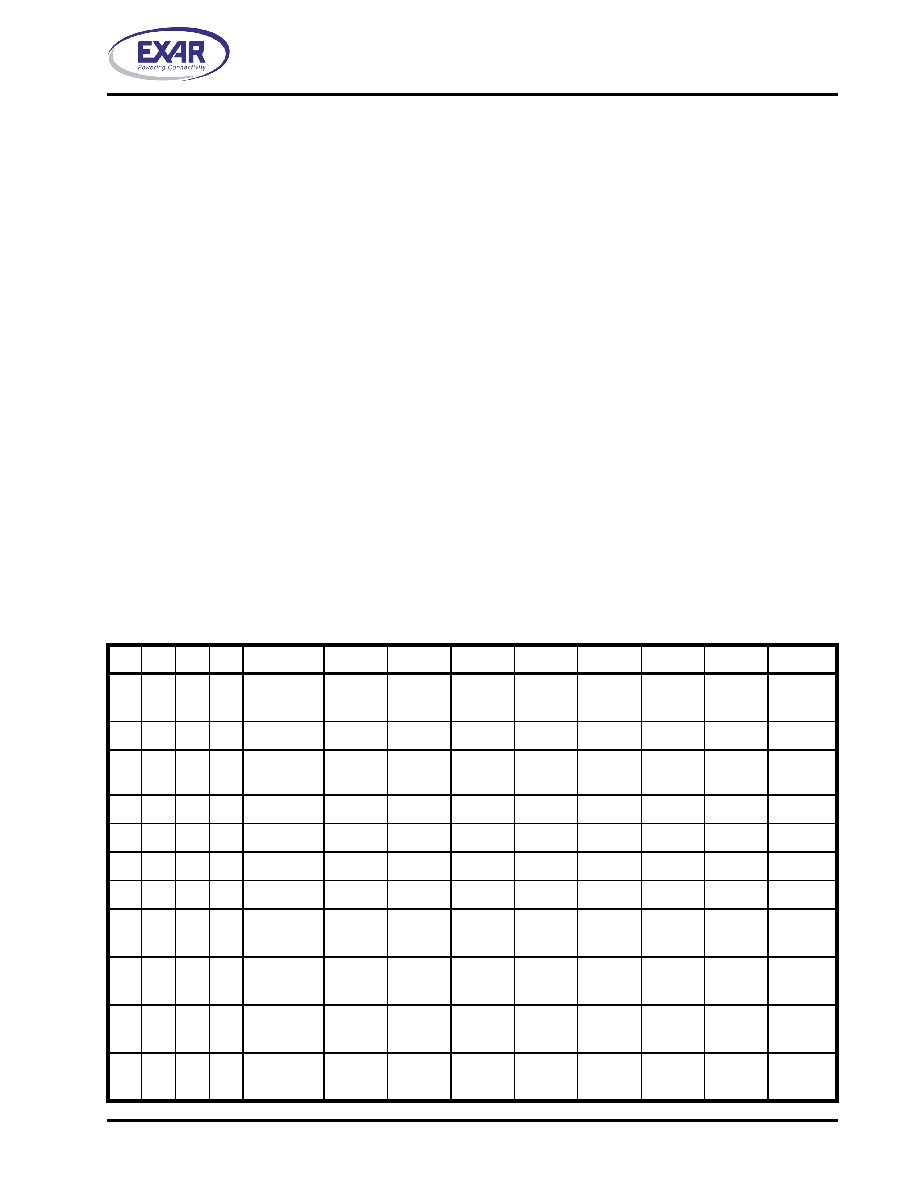
TABLE 5: INTERNAL REGISTERS DESCRIPTION
0
Data Port ,
ECP-AFIFO
PD7
PD6
PD5
PD4
PD3
PD2
PD1
PD0
0
1
DSR
BUSY
-ACK
PE
SLCT
ERROR
1
0
1
0
DCR
0
DIR
INT
enable
-SLCTIN
INIT
-AUTO-
FD
-STROBE
0
1
EPP-APort
AP-7
AP-6
AP-5
AP-4
AP-3
AP-2
AP-1
AP-0
1
0
EPP-DPort
PDA-7
PDA-6
PDA-5
PDA-4
PDA-3
PDA-2
PDA-1
PDA-0
0
1
0
1
EPP-DPort
PDB-7
PDB-6
PDB-5
PDB-4
PDB-3
PDB-2
PDB-1
PDB-0
0
1
0
EPP-DPort
PDC-7
PDC-6
PDC-5
PDC-4
PDC-3
PDC-2
PDC-1
PDC-0
0
1
EPP-DPort
PDD-7
PDD-6
PDD-5
PDD-4
PDD-3
PDD-2
PDD-1
PDD-0
1
X
0
CONF-A
ECP
INT type
0
1
0
FIFO-F
0
1
X
0
1
CONF-B
RLE
IRQ
Input
IRQ
Sel-2
IRQ
Sel-1
IRQ
Sel-0
DMA
Sel-2
DMA
Sel-1
DMA
Sel-0
1
X
1
0
ECR
MODE
Sel-2
MODE
Sel-1
MODE
Sel-0
FAULT
enable
DMA
En/Dis
Service
INT
FIFO
full
FIFO
empty
A10 A2
A1
A0 REGISTER
D7D6D5D4D3D2D1
D0
相关PDF资料 |
PDF描述 |
|---|---|
| XR16L2550IMTR-F | IC UART FIFO 16B DUAL 48TQFP |
| XR16M780IL32-F | IC UART FIFO 64B 32QFN |
| XR68M752IL32TR-F | IC UART FIFO 64B DUAL 32QFN |
| ATMEGA168-15AT | MCU AVR 16K FLASH 15MHZ 32-TQFP |
| ST16C450CQ48TR-F | IC UART SINGLE 48TQFP |
相关代理商/技术参数 |
参数描述 |
|---|---|
| ST78C36CQ-0A-EVB | 功能描述:界面开发工具 Supports 78C36 64 ld TQFP, ISA Interface RoHS:否 制造商:Bourns 产品:Evaluation Boards 类型:RS-485 工具用于评估:ADM3485E 接口类型:RS-485 工作电源电压:3.3 V |
| ST78C36CQ64 | 制造商:Rochester Electronics LLC 功能描述: 制造商:Exar Corporation 功能描述: |
| ST78C36CQ64-F | 功能描述:接口 - 专用 UART RoHS:否 制造商:Texas Instruments 产品类型:1080p60 Image Sensor Receiver 工作电源电压:1.8 V 电源电流:89 mA 最大功率耗散: 最大工作温度:+ 85 C 安装风格:SMD/SMT 封装 / 箱体:BGA-59 |
| ST78L05 | 制造商:SEMTECH_ELEC 制造商全称:SEMTECH ELECTRONICS LTD. 功能描述:3-Terminal positive voltage regulator |
| ST78L05U | 制造商:SEMTECH_ELEC 制造商全称:SEMTECH ELECTRONICS LTD. 功能描述:3-Terminal Positive Voltage Regulator |
发布紧急采购,3分钟左右您将得到回复。