- 您现在的位置:买卖IC网 > PDF目录69375 > ST7L35UC/XXXX (STMICROELECTRONICS) 8-BIT, MROM, 8 MHz, MICROCONTROLLER, QCC20 PDF资料下载
参数资料
| 型号: | ST7L35UC/XXXX |
| 厂商: | STMICROELECTRONICS |
| 元件分类: | 微控制器/微处理器 |
| 英文描述: | 8-BIT, MROM, 8 MHz, MICROCONTROLLER, QCC20 |
| 封装: | 5 X 6 MM, ROHS COMPLIANT, QFN-20 |
| 文件页数: | 169/236页 |
| 文件大小: | 2064K |
| 代理商: | ST7L35UC/XXXX |
第1页第2页第3页第4页第5页第6页第7页第8页第9页第10页第11页第12页第13页第14页第15页第16页第17页第18页第19页第20页第21页第22页第23页第24页第25页第26页第27页第28页第29页第30页第31页第32页第33页第34页第35页第36页第37页第38页第39页第40页第41页第42页第43页第44页第45页第46页第47页第48页第49页第50页第51页第52页第53页第54页第55页第56页第57页第58页第59页第60页第61页第62页第63页第64页第65页第66页第67页第68页第69页第70页第71页第72页第73页第74页第75页第76页第77页第78页第79页第80页第81页第82页第83页第84页第85页第86页第87页第88页第89页第90页第91页第92页第93页第94页第95页第96页第97页第98页第99页第100页第101页第102页第103页第104页第105页第106页第107页第108页第109页第110页第111页第112页第113页第114页第115页第116页第117页第118页第119页第120页第121页第122页第123页第124页第125页第126页第127页第128页第129页第130页第131页第132页第133页第134页第135页第136页第137页第138页第139页第140页第141页第142页第143页第144页第145页第146页第147页第148页第149页第150页第151页第152页第153页第154页第155页第156页第157页第158页第159页第160页第161页第162页第163页第164页第165页第166页第167页第168页当前第169页第170页第171页第172页第173页第174页第175页第176页第177页第178页第179页第180页第181页第182页第183页第184页第185页第186页第187页第188页第189页第190页第191页第192页第193页第194页第195页第196页第197页第198页第199页第200页第201页第202页第203页第204页第205页第206页第207页第208页第209页第210页第211页第212页第213页第214页第215页第216页第217页第218页第219页第220页第221页第222页第223页第224页第225页第226页第227页第228页第229页第230页第231页第232页第233页第234页第235页第236页
Supply, reset and clock management
ST7L34, ST7L35, ST7L38, ST7L39
Doc ID 11928 Rev 7
7
Supply, reset and clock management
The device includes a range of utility features for securing the application in critical
situations (for example, in case of a power brown-out) and reducing the number of external
components.
Main features
●
Clock management
–
1 MHz internal RC oscillator (enabled by option byte)
–
1 to 16 MHz or 32 kHz external crystal/ceramic resonator (selected by option byte)
–
External clock input (enabled by option byte)
–
PLL for multiplying the frequency by 8(enabled by option byte)
●
Reset sequence manager (RSM)
●
System integrity management (SI)
–
Main supply low voltage detection (LVD)with reset generation (enabled by option
byte)
–
Auxiliary voltage detector (AVD) with interrupt capability for monitoring the main
supply (enabled by option byte)
7.1
Internal RC oscillator adjustment
The device contains an internal RC oscillator with high accuracy for a given device,
temperature and voltage. It must be calibrated to obtain the frequency required in the
application. This is done by the software writing an 8-bit calibration value in the RCCR (RC
control register) and in the bits [6:5] in the SICSR (SI control status register).
Whenever the microcontroller is reset, the RCCR returns to its default value (FFh), that is,
each time the device is reset, the calibration value must be loaded in the RCCR. Predefined
calibration values are stored in EEPROM for 3.3 V and 5 V VDD supply voltages at 25°C, as
shown in Table 7.
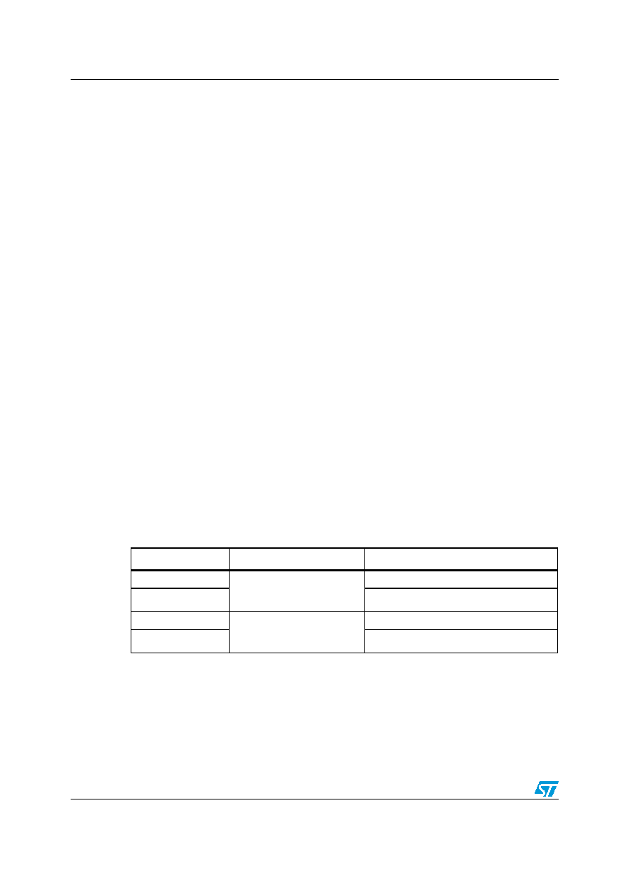
Table 7.
RCCR calibration registers
RCCR
Conditions
ST7L3 addresses
RCCRH0
VDD = 5 V
TA = 25°C
fRC = 1 MHz
(1)
1.
RCCR0 and RCCR1 calibrated within these conditions in order to reach RC accuracy as mentioned in
Table 101: Operating conditions (tested for TA = -40 to +125 °C) @ VDD = 4.5 to 5.5 V on page 185 and
DEE0h(2) (CR[9:2] bits)
2.
DEE0h, DEE1h, DEE2h and DEE3h addresses are located in a reserved area but are special bytes
containing also the RC calibration values which are read-accessible only in user mode. If all the EEPROM
data or Flash space (including the RC calibration values locations) has been erased (after the readout
protection removal), then the RC calibration values can still be obtained through these four addresses.
For compatibility reasons with the SICSR register, CR[1:0] bits are stored in the fifth and sixth positions of
DEE1 and DEE3 addresses.
RCCRL0
DEE1h(2) (CR[1:0] bits)
RCCRH1
VDD = 3.3 V
TA = 25°C
DEE2h(2)(CR[9:2] bits)
RCCRL1
DEE3h(2) (CR[1:0] bits)
相关PDF资料 |
PDF描述 |
|---|---|
| ST7L39MA/XXXRS | 8-BIT, EEPROM, 8 MHz, MICROCONTROLLER, PDSO20 |
| ST7PL34UA/XXXRE | 8-BIT, MROM, 8 MHz, MICROCONTROLLER, QCC20 |
| ST7PL39MA/XXXRE | 8-BIT, EEPROM, 8 MHz, MICROCONTROLLER, PDSO20 |
| ST7FL38F2MCE | 8-BIT, FLASH, 8 MHz, MICROCONTROLLER, PDSO20 |
| ST7PL35MA/XXXX | 8-BIT, MROM, 8 MHz, MICROCONTROLLER, PDSO20 |
相关代理商/技术参数 |
参数描述 |
|---|---|
| ST7LCRDIE6 | 制造商:STMICROELECTRONICS 制造商全称:STMicroelectronics 功能描述:Full-speed USB MCU with smartcard interface |
| ST7LCRDIE6/XXX | 制造商:STMICROELECTRONICS 制造商全称:STMicroelectronics 功能描述:Full-speed USB MCU with smartcard interface |
| ST7LCRE4U1 | 制造商:STMICROELECTRONICS 制造商全称:STMicroelectronics 功能描述:Full-speed USB MCU with smartcard interface |
| ST7LCRE4U1/XXX | 制造商:STMICROELECTRONICS 制造商全称:STMicroelectronics 功能描述:Full-speed USB MCU with smartcard interface |
| ST7LITE0 | 制造商:STMICROELECTRONICS 制造商全称:STMicroelectronics 功能描述:8-BIT MCU WITH SINGLE VOLTAGE FLASH MEMORY, DATA EEPROM, ADC, TIMERS, SPI |
发布紧急采购,3分钟左右您将得到回复。