- 您现在的位置:买卖IC网 > PDF目录98146 > ST90135M5T6 (STMICROELECTRONICS) 16-BIT, MROM, 24 MHz, MICROCONTROLLER, PQFP80 PDF资料下载
参数资料
| 型号: | ST90135M5T6 |
| 厂商: | STMICROELECTRONICS |
| 元件分类: | 微控制器/微处理器 |
| 英文描述: | 16-BIT, MROM, 24 MHz, MICROCONTROLLER, PQFP80 |
| 封装: | PLASTIC, TQFP-80 |
| 文件页数: | 166/199页 |
| 文件大小: | 3266K |
| 代理商: | ST90135M5T6 |
第1页第2页第3页第4页第5页第6页第7页第8页第9页第10页第11页第12页第13页第14页第15页第16页第17页第18页第19页第20页第21页第22页第23页第24页第25页第26页第27页第28页第29页第30页第31页第32页第33页第34页第35页第36页第37页第38页第39页第40页第41页第42页第43页第44页第45页第46页第47页第48页第49页第50页第51页第52页第53页第54页第55页第56页第57页第58页第59页第60页第61页第62页第63页第64页第65页第66页第67页第68页第69页第70页第71页第72页第73页第74页第75页第76页第77页第78页第79页第80页第81页第82页第83页第84页第85页第86页第87页第88页第89页第90页第91页第92页第93页第94页第95页第96页第97页第98页第99页第100页第101页第102页第103页第104页第105页第106页第107页第108页第109页第110页第111页第112页第113页第114页第115页第116页第117页第118页第119页第120页第121页第122页第123页第124页第125页第126页第127页第128页第129页第130页第131页第132页第133页第134页第135页第136页第137页第138页第139页第140页第141页第142页第143页第144页第145页第146页第147页第148页第149页第150页第151页第152页第153页第154页第155页第156页第157页第158页第159页第160页第161页第162页第163页第164页第165页当前第166页第167页第168页第169页第170页第171页第172页第173页第174页第175页第176页第177页第178页第179页第180页第181页第182页第183页第184页第185页第186页第187页第188页第189页第190页第191页第192页第193页第194页第195页第196页第197页第198页第199页
Obsolete
Product(s)
- Obsolete
Product(s)
Obsolete
Product(s)
- Obsolete
Product(s)
69/199
ST90158 - RESET AND CLOCK CONTROL UNIT (RCCU)
CLOCK MANAGEMENT (Cont’d)
6.3.1 PLL Clock Multiplier Programming
The CLOCK1 signal generated by the oscillator
drives a programmable divide-by-two circuit. If the
DIV2 control bit in MODER is set (Reset Condi-
tion), CLOCK2, is equal to CLOCK1 divided by
two; if DIV2 is reset, CLOCK2 is identical to
CLOCK1. Since the input clock to the Clock Multi-
plier circuit requires a 50% duty cycle for correct
PLL operation, the divide by two circuit should be
enabled when a crystal oscillator is used, or when
the external clock generator does not provide a
50% duty cycle. In practice, the divide-by-two is
virtually always used in order to ensure a 50% duty
cycle signal to the PLL multiplier circuit.
When the PLL is active, it multiplies CLOCK2 by 6,
8, 10 or 14, depending on the status of the MX0 -1
bits in PLLCONF. The multiplied clock is then di-
vided by a factor in the range 1 to 7, determined by
the status of the DX0-2 bits; when these bits are
programmed to 111, the PLL is switched off.
Following a RESET phase, programming bits
DX0-2 to a value different from 111 will turn the
PLL on. After allowing a stabilisation period for the
PLL,
setting
the
CSU_CKSEL
bit
in
the
CLK_FLAG Register selects the multiplier clock.
The maximum frequency allowed for INTCLK is 24
MHz for 5V operation, and 16 MHz for 3V opera-
tion. Care is required, when programming the PLL
multiplier and divider factors, not to exceed the
maximum permissible operating frequency for
INTCLK, according to supply voltage.
The ST9 being a static machine, there is no lower
limit for INTCLK. However, below 1MHz, A/D con-
verter precision (if present) decreases.
6.3.2 CPU Clock Prescaling
The system clock, INTCLK, which may be the out-
put of the PLL clock multiplier, CLOCK2, CLOCK2/
16 or CK_AF, drives a programmable prescaler
which generates the basic time base, CPUCLK,
for the instruction executer of the ST9 CPU core.
This allows the user to slow down program execu-
tion during non processor intensive routines, thus
reducing power dissipation.
The internal peripherals are not affected by the
CPUCLK prescaler and continue to operate at the
full INTCLK frequency. This is particularly useful
when little processing is being done and the pe-
ripherals are doing most of the work.
The prescaler divides the input clock by the value
programmed in the control bits PRS2,1,0 in the
MODER register. If the prescaler value is zero, no
prescaling takes place, thus CPUCLK has the
same period and phase as INTCLK. If the value is
different from 0, the prescaling is equal to the val-
ue plus one, ranging thus from two (PRS2,1,0 = 1)
to eight (PRS2,1,0 = 7).
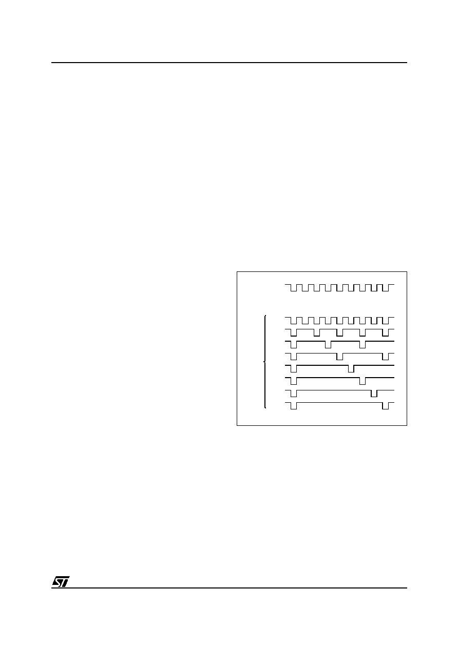
The clock generated is shown in Figure 33, and it
will be noted that the prescaling of the clock does
not preserve the 50% duty cycle, since the high
level is stretched to replace the missing cycles.
This is analogous to the introduction of wait cycles
for access to external memory. When External
Memory Wait or Bus Request events occur, CPU-
CLK is stretched at the high level for the whole pe-
riod required by the function.
Figure 33. CPU Clock Prescaling
6.3.3 Peripheral Clock
The system clock, INTCLK, which may be the out-
put of the PLL clock multiplier, CLOCK2, CLOCK2/
16 or CK_AF, is also routed to all ST9 on-chip pe-
ripherals and acts as the central timebase for all
timing functions.
INTCLK
CPUCLK
VA00260
000
001
010
011
100
101
110
111
PRS VALUE
9
相关PDF资料 |
PDF描述 |
|---|---|
| ST90T158M9Q6 | 16-BIT, OTPROM, 24 MHz, MICROCONTROLLER, PQFP80 |
| ST90158M9Q6 | 16-BIT, MROM, 24 MHz, MICROCONTROLLER, PQFP80 |
| ST9020B6/XX | 16-BIT, MROM, 24 MHz, MICROCONTROLLER, PDIP40 |
| ST9027B6/XX | 16-BIT, MROM, 24 MHz, MICROCONTROLLER, PDIP40 |
| ST9036C6 | 16-BIT, MROM, 24 MHz, MICROCONTROLLER, PQCC68 |
相关代理商/技术参数 |
参数描述 |
|---|---|
| ST90135M6 | 制造商:未知厂家 制造商全称:未知厂家 功能描述:8/16-BIT MICROCONTROLLER (MCU) WITH 16 TO 64K ROM. OTP OR EPROM. 512 TO 2K RAM - ST9 + FAMILY |
| ST90135M6LVT6 | 制造商:未知厂家 制造商全称:未知厂家 功能描述:8/16-BIT MICROCONTROLLER (MCU) WITH 16 TO 64K ROM. OTP OR EPROM. 512 TO 2K RAM - ST9 + FAMILY |
| ST90135M6Q6 | 制造商:STMICROELECTRONICS 制造商全称:STMicroelectronics 功能描述:8/16-BIT MCU FAMILY WITH UP TO 64K ROM/OTP/EPROM AND UP TO 2K RAM |
| ST90135M6T6 | 制造商:STMICROELECTRONICS 制造商全称:STMicroelectronics 功能描述:8/16-BIT MCU FAMILY WITH UP TO 64K ROM/OTP/EPROM AND UP TO 2K RAM |
| ST9014 | 制造商:SEMTECH_ELEC 制造商全称:SEMTECH ELECTRONICS LTD. 功能描述:NPN Silicon Epitaxial Planar Transistor |
发布紧急采购,3分钟左右您将得到回复。