- 您现在的位置:买卖IC网 > PDF目录372330 > STEL-1377Q FREQUENCY SYNTHESIZER|DIP|64PIN|PLASTIC PDF资料下载
参数资料
| 型号: | STEL-1377Q |
| 英文描述: | FREQUENCY SYNTHESIZER|DIP|64PIN|PLASTIC |
| 中文描述: | 频率合成器|双酯| 64管脚|塑料 |
| 文件页数: | 16/19页 |
| 文件大小: | 284K |
| 代理商: | STEL-1377Q |
STEL-2060C
16
NODE SYNCHRONIZATION
In a communication system using Viterbi decoding the de-
coder will only operate correctly when the symbols G1 and
G2 are loaded into the decoder in the correct order. Identi-
fying which symbol is G1 and which one is G2 is referred to
as node synchronization. The STEL-2060C contains a circuit
designed to carry out the node synchronization function
automatically. It uses the internally generated metrics of the
received sequence to do this. These constantly changing
parameters are periodically renormalized to keep them
within bounds. If renormalization occurs too frequently it is
a good indication that the system is not converging, most
likely due to lack of node synchronization. The renormal-
ization rate at which the system will decide to change the
node sync is determined by the threshold parameter. This is
an 8-bit number which is set by the
THR
7-0
inputs. When the
renormalization count exceeds this value, the
OOS
output
will go high and the
AUTO
output will pulse high for one
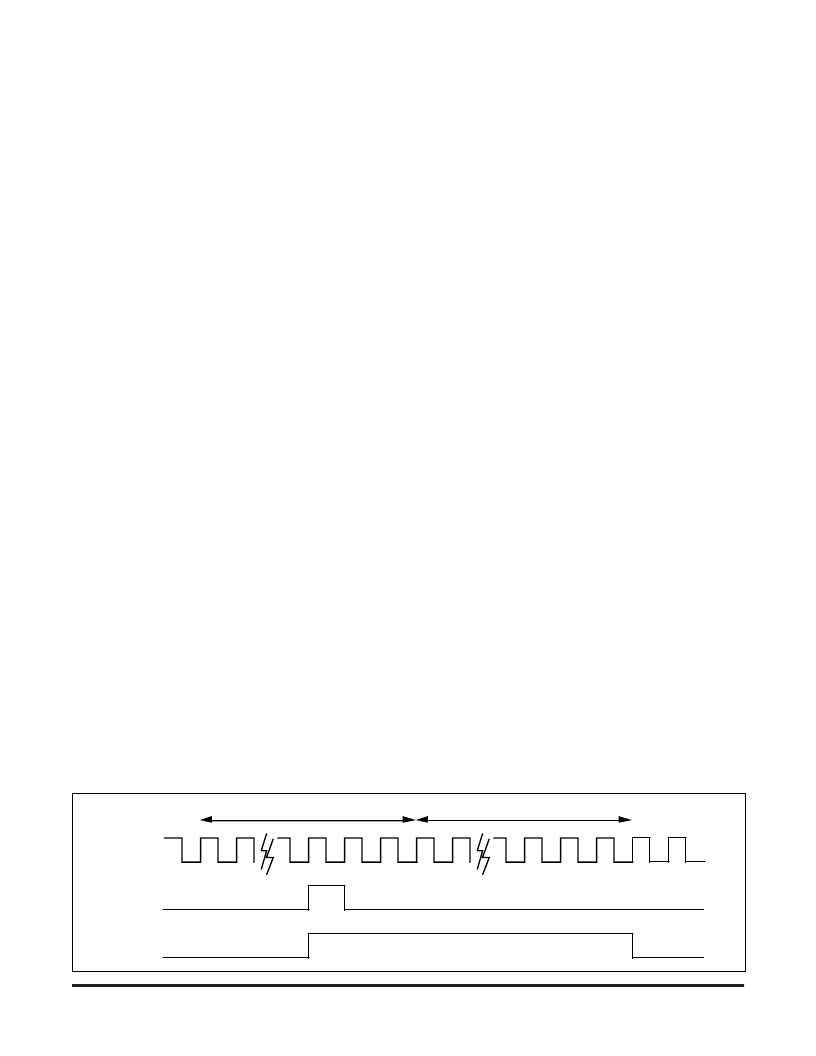
clock cycle, as shown during Count Window N in the timing
diagram below. The counter is reset after a number of bits
determined by the number set by the
COUNT
7-0
inputs, so
that the threshold must be exceeded somewhere in that
period for resynchronization to take place.
OOS
will be
reset if the counter then counts through an entire window
and the threshold is not exceeded, as shown during Count
Window N + 1 in the timing diagram below. The most
suitable threshold setting will depend on the value of
E
b
/N
0
, the coding rate, and the signal level at the G1 and G2
inputs. For full scale inputs, i.e., the peak signal values
almost saturate the digital inputs, suitable starting values
for the threshold will be 1% for Rate
1
/
2
, 0.5% for Rates
2
/
3
to
6
/
7
, and 0.1% for Rate
7
/
8
. e.g., for Rate
1
/
2
, if the number of
bits over which the measure is made is set to 512
(
COUNT
= 01
) the threshold should be set to 5. Setting
THR
= 0 gives a value of 6, which is adequately close.
More reliable results will be obtained by counting over a
longer period to improve the averaging process, but this
increases the time taken to make a decision and hence to
acquire node sync. Thus, starting with a low count period
and then increasing it (and adjusting the threshold accord-
ingly to maintain a value of 1%) when
OOS
goes low will
result in a faster acquisition of correct node sync with a
lower probability of accidental loss of node sync once cor-
rect sync has been achieved. To use the internal node sync
the
AUTO
output must be connected to the
SYNC
input.
The synchronization sequence depends on the setting of the
PARL
input. When
PARL
is set low it is assumed that the
data was modulated using BPSK, and when it is set high it is
assumed that the data was modulated using QPSK. The
appropriate synchronization sequences will be invoked, as
shown in the node sync sequence tables. Note that the
pipeline delay through the device will be affected by the
node sync state. If multiple devices are used in parallel to
achieve higher data rates, it is necessary for the all devices to
have the same node sync state to equalize their pipeline
delays. It will be necessary to reset the devices together to
achieve this state
When internal depuncturing is used, additional node sync
states exist because of the uncertainty of the current symbol
position in the puncture sequence. In this case the node sync
circuit will also search through the sequence by adding
delays in the depuncturing process to precess through the
sequence. In the sequential input mode (
PARL
= 0) this is
simply an extension of the node sync process, since the
alternate state is achieved by delaying the symbols. In the
parallel input mode, however, this is different from the
"invert G2 and swap" process, and in this sync sequence
"invert G2 and swap" precedes the delay addition, so that
the system goes through both the initial and alternate states
for each delay addition tried. This is shown for the Rate
2
/
3
case. In each case the symbols are read into the depunc-
turing circuit in groups of three (in the BPSK mode) or six (in
the QPSK mode) and attempts are made to reinsert the
punctured symbol in all of the possible insertion positions.
The positions of the punctured symbols in the sequences are
shown by the asterisks (*). The resulting groups of four or
eight symbols are then decoded in pairs, resulting in two
decoded bits in the BPSK mode and four bits in the QPSK
mode. For higher rates the sequences will be extensions of
this procedure.
When external depuncturing is used, the determination of
which symbols were punctured, and need to be reinserted
into the symbol sequence, is part of the node sync process.
This is because the acquisition of correct node sync cannot be
completed until the punctured symbols are reinserted cor-
rectly. The
AUTO
and
OOS
outputs of the STEL-2060C can
be used as indicators of the operation of the internal node
sync process;
OOS
will remain high as long as node sync has
not been achieved and
AUTO
will pulse each time a new
node sync state is being tried. Since there are only two
possible internal node sync states, alternate pulses on the
AUTO
output can be used as an indication that the depunc-
turing is incorrect and a new depuncturing sequence should
be tried externally.
NODE SYNC TIMING
AUTO
OOS
ODCLK
Count Window N
Count Window N+1
Powered by ICminer.com Electronic-Library Service CopyRight 2003
相关PDF资料 |
PDF描述 |
|---|---|
| STEL-1377S | FREQUENCY SYNTHESIZER|DIP|64PIN|PLASTIC |
| STEL-1378A | FREQUENCY SYNTHESIZER|HYBRID|DIP|64PIN|PLASTIC |
| STEPHY1 | Semiconductor Fuse; Current Rating:35A; Voltage Rating:250V; Fuse Type:Fast Acting; Fuse Terminals:Blade; Diameter:20.6mm; Length:81mm; Series:L25S; Voltage Rating:250V |
| STF201-22.TC | Semiconductor Fuse; Current Rating:50A; Voltage Rating:250V; Fuse Type:Fast Acting; Fuse Terminals:Blade; Diameter:20.6mm; Length:81mm; Series:L25S; Voltage Rating:250V |
| STF201-30.TC | Triac; Thyristor Type:Sensitive Gate; Peak Repetitive Off-State Voltage, Vdrm:200V; On-State RMS Current, IT(rms):800mA; Gate Trigger Current (QI), Igt:5mA; Current, It av:0.8A; Leaded Process Compatible:Yes RoHS Compliant: Yes |
相关代理商/技术参数 |
参数描述 |
|---|---|
| STEL-1377S | 制造商:未知厂家 制造商全称:未知厂家 功能描述:FREQUENCY SYNTHESIZER|DIP|64PIN|PLASTIC |
| STEL-1378A | 制造商:未知厂家 制造商全称:未知厂家 功能描述:FREQUENCY SYNTHESIZER|HYBRID|DIP|64PIN|PLASTIC |
| STEL-2000A+20/CR | 制造商:未知厂家 制造商全称:未知厂家 功能描述:RF MODULATOR/DEMODULATOR|CMOS|QFP|100PIN|PLASTIC |
| STEL-2000A+45/CR | 制造商:未知厂家 制造商全称:未知厂家 功能描述:RF MODULATOR/DEMODULATOR|CMOS|QFP|100PIN|PLASTIC |
| STEL2020 | 制造商:未知厂家 制造商全称:未知厂家 功能描述:Convolutional-FEC-Viterbi Error Circuit - Burst and continuous modes |
发布紧急采购,3分钟左右您将得到回复。