参数资料
| 型号: | STK433-040N-E |
| 厂商: | ON Semiconductor |
| 文件页数: | 2/11页 |
| 文件大小: | 0K |
| 描述: | IC HYBRID MOD AUD PWR AMP AB 2CH |
| 标准包装: | 25 |
| 类型: | AB 类 |
| 输出类型: | 2 通道(立体声) |
| 在某负载时最大输出功率 x 通道数量: | 40W x 2 @ 6 欧姆 |
| 电源电压: | 0 V ~ 38 V |
| 特点: | 静音,待机 |
| 安装类型: | * |
| 供应商设备封装: | * |
| 封装/外壳: | * |
| 包装: | * |
STK433-040N-E
No.A2101-10/11
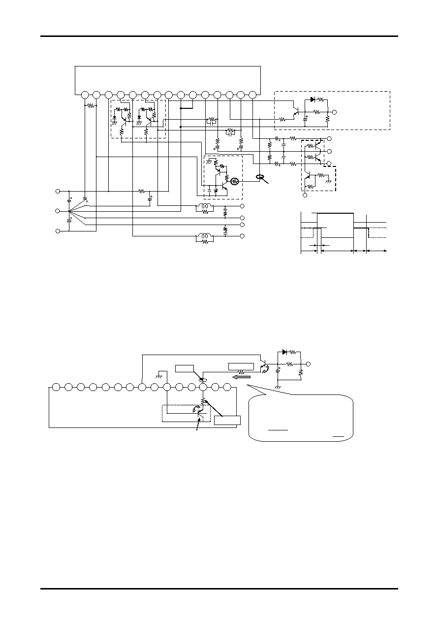
STK433-000N-E/100N-E series Stand-by Control & Mute Control & Load-Short
Protection Application
[STK433-000N-E/100N-E series Stand-By Control Example]
[Feature]
The pop noise which occurs to the time of power supply on/off can be improved substantially by recommendation
Stand-By Control Application.
Stand-By Control can be done by additionally adjusting the limitation resistance to the voltage such as micom, the set
design is easy.
(Reference circuit) STK433-000N-E/100N-E series test circuit To Stand-By Control added +5V.
[Operation explanation] #13pin Stand-By Control Voltage VST
(1) Operation Mode
The switching transistor in the bias circuit turns on and places the amplifier into the operating mode, when 13pin
(VST) voltage added above 2.5V (typ 3.0V).
(2) Stand-By Mode
When 13pin (VST) voltage is stopped (= 0V), the switching transistor in the bias circuit turn off, placing the
amplifier into the standby mode.
(*1) The current limiting resistor must be used to ensure that stand-by pin (13pin) voltage does not exceed its
maximum rated value VST max.
(*2) The pop noise level when the power is turned on can be reduced by setting the time constant with a capacitor
in operating mode.
(*3) Determines the time constant at which the capacitor (*2) is discharged in stand-by mode.
GND
+Vcc
-Vcc
STK433-000N-E/100N-E series
Ch2 OUT
Ch1 OUT
GND
Ch1 IN
+Vcc
Ch1
IN
Ch1
NF
Ch2
IN
Ch2
NF
Ch2
OUT
Ch1
OUT
-Vcc
SUB
GND
+PRE
ST-BY
GND
10k
2.2k
Mute Control
H : Single Mute
L : Normal
Stand-by Control(ex)
H:Operation Mode(+5V)
L:Stand-by Mode(0V)
(*1) Please use restriction resistance as there is no Stand-by
terminal voltage (#13pin) beyond maximun rating (VSTmax).
Ch1
OUT
Ch2
OUT
56k
33
F
/10V
33k
1k
2k
2
3
4
5
8
7
6
9
10
11 12 13 14 15
1
-PRE
56k
0.
2
56k
6.8k
0.
2
56k
(*1)
2.7k
10k
R1
(*4)
56k
1k
22k
0.1
F
Load Short Protection
Circuit
Latch Up
Circuit
V1
(*4) R1 is changed depending on the power-supply voltage(-Vcc).
Please set resistance(R1) to become [V1=0v] by the following calculation types.
Ch2 IN
+5V
Stand-by
Control
Mute
Control
ST-BY
PLAY
ST-BY
MUTE
ex)Stand-By Control Voltage VST=+5v
VST is set by the limitation resistance(*1).
IST =(VST-VBE*2)/((*1)+(*2))
=(5v-0.6v*2)/(4.7k+2.7k)
=0.513(mA)
VST=IST×4.7k+VBE=0.513×4.7k+0.6=3.0(V)
STK433-000N-E/100N-E series
+Vcc
Ch1
IN
Ch1
NF
Ch2
IN
Ch2
NF
Ch2
OUT
Ch1
OUT
-Vcc
SUB/
GND
IC
GND
+PRE
ST-BY
Ch1
OUT
Ch2
OUT
Stand-By Circuit
in PreDriver IC
VBE
Stand-by Control
H : Operation Mode(+5V)
L : Stand-by Mode(0V)
2.7K(*1)
33μF
(*2)
33k
1k
(*3)
2k
(*3)
IST
VBE
-PRE
4.7k(*2)
#13pin Stand-By OFF threshold.
Switching transistor
in the bias circuit
1
2
3
4
7
6
5
8
9
10
11 12 13 14 15
VST
相关PDF资料 |
PDF描述 |
|---|---|
| STK433-130N-E | IC HYBRID MOD AUD PWR AMP AB 2CH |
| SX8652IWLTRT | IC TOUCH SCREEN CTRLR 14DFN |
| SX8654IWLTRT | IC TOUCH SCREEN 12BIT 20QFN |
| SX8657IWLTRT | IC TOUCH SCREEN 12BIT 20QFN |
| SY100E222LTI TR | IC CLOCK GEN 1:15 BUFFER 52-LQFP |
相关代理商/技术参数 |
参数描述 |
|---|---|
| STK433-060-E | 制造商:SANYO Semiconductor Co Ltd 功能描述:Thick Film Hybrid IC 2 Channel Class AB Audio Power IC, 50W x2 |
| STK433-060N-E | 功能描述:音频放大器 RoHS:否 制造商:STMicroelectronics 产品:General Purpose Audio Amplifiers 输出类型:Digital 输出功率: THD + 噪声: 工作电源电压:3.3 V 电源电流: 最大功率耗散: 最大工作温度: 安装风格:SMD/SMT 封装 / 箱体:TQFP-64 封装:Reel |
| STK433-070-E | 制造商:SANYO Semiconductor Co Ltd 功能描述:Thick Film Hybrid IC 2 Channel Class AB Audio Power IC, 60W x2 |
| STK433-070G-E | 制造商:ON Semiconductor 功能描述:AF POWER AMPLIFIE - Tape and Reel |
| STK433-070GN-E | 功能描述:音频放大器 RoHS:否 制造商:STMicroelectronics 产品:General Purpose Audio Amplifiers 输出类型:Digital 输出功率: THD + 噪声: 工作电源电压:3.3 V 电源电流: 最大功率耗散: 最大工作温度: 安装风格:SMD/SMT 封装 / 箱体:TQFP-64 封装:Reel |
发布紧急采购,3分钟左右您将得到回复。