参数资料
| 型号: | SY69753LHI |
| 厂商: | Micrel Inc |
| 文件页数: | 7/13页 |
| 文件大小: | 0K |
| 描述: | IC CLOCK/DATA REC 155MBPS 32TQFP |
| 标准包装: | 250 |
| 类型: | 时钟和数据恢复(CDR),多路复用器 |
| PLL: | 是 |
| 主要目的: | 以太网,SONET/SDH,ATM OC-3 |
| 输入: | PECL |
| 输出: | PECL |
| 电路数: | 1 |
| 比率 - 输入:输出: | 1:3 |
| 差分 - 输入:输出: | 是/是 |
| 频率 - 最大: | 155Mbps |
| 电源电压: | 3.15 V ~ 3.45 V |
| 工作温度: | -40°C ~ 85°C |
| 安装类型: | 表面贴装 |
| 封装/外壳: | 32-TQFP 裸露焊盘 |
| 供应商设备封装: | 32-EPAD-TQFP |
| 包装: | 托盘 |
Micrel, Inc.
SY69753L
December 2007
3
M9999-120307-F
hbwhelp@micrel.com or (408) 955-1690
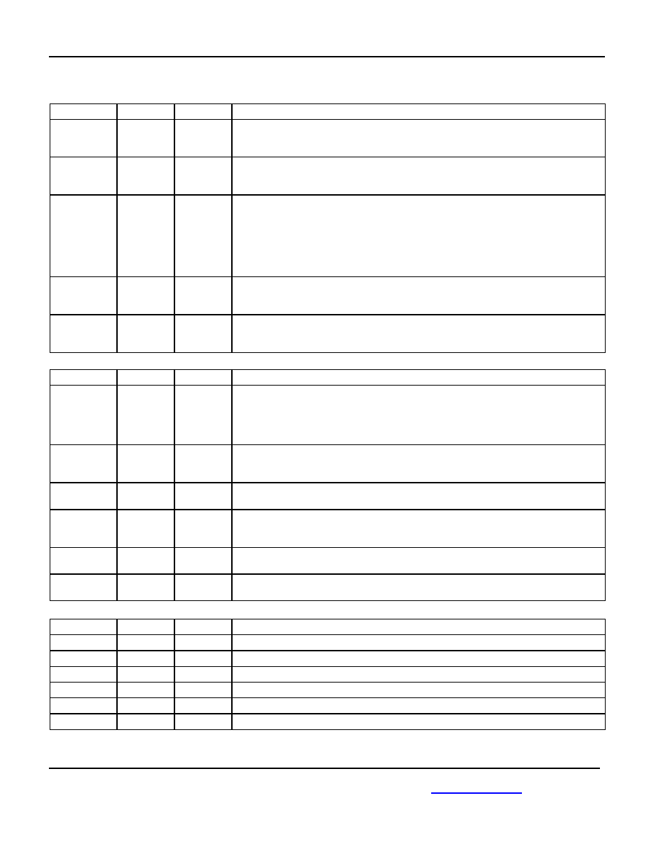
Pin Description
Inputs
Pin Number
Pin Name
Type
Pin Name
2
3
RDINP
RDINN
Differential
PECL
Serial Data Input: These built-in line receiver inputs are connected to the differential
receive serial data stream. An internal receive PLL recovers the embedded clock
(RCLK) and data (RDOUT) information.
5
REFCLK
TTL Input
Reference Clock: This input is used as the reference for the internal frequency
synthesizer and the "training" frequency for the receiver PLL to keep it centered in the
absence of data coming in on the RDIN inputs.
26
CD
PECL
Input
Carrier Detect: This input controls the recovery function of the Receive PLL and can be
driven by the carrier detect output of optical modules or from external transition
detection circuitry. When this input is HIGH, the input data stream (RDIN) is recovered
normally by the Receive PLL. When this input is LOW the data on the inputs RDIN will
be internally forced to a constant LOW, the data outputs RDOUT will remain LOW, the
Link Fault Indicator output LFIN forced LOW and the clock recovery PLL forced to look
onto the clock frequency generated from REFCLK.
32
25
DIVSEL1
DIVSEL2
TTL Input
Divider Select: These inputs select the ratio between the output clock frequency
(RCLK/TCLK) and the REFCLK input frequency as shown in the “Reference Frequency
Selection” table.
16
CLKSEL
TTL Input
Clock Select: This input is used to select either the recovered clock of the receiver PLL
(CLKSEL = HIGH) or the clock of the frequency synthesizer (CLKSEL = LOW) to the
TCLK outputs.
Outputs
Pin Number
Pin Name
Type
Pin Name
31
LFIN
TTL
Output
Link Fault Indicator: This output indicates the status of the input data stream RDIN.
Active HIGH signal is indicating when the internal clock recovery PLL has locked onto
the incoming data stream. LFIN will go HIGH if CD is HIGH and RDIN is within the
frequency range of the Receive PLL (1000ppm) and will be alternating if not. LFIN is an
asynchronous output.
23
24
RDOUTN
RDOUTP
Differential
PECL
Receive Data Output: These ECL 100K outputs represent the recovered data from the
input data stream (RDIN). This recovered data is specified against the rising edge of
RCLK.
20
21
RCLKN
RCLKP
Differential
PECL
Clock Output: These ECL 100K outputs represent the recovered clock used to sample
the recovered data (RDOUT).
18
17
TCLKP
TCLKN
Differential
PECL
Clock Output: These ECL 100K outputs represent either the recovered clock (CLKSEL
= HIGH) used to sample the recovered data (RDOUT) or the transmit clock of the
frequency synthesizer (CLKSEL = LOW).
9
10
PLLSP
PLLSN
Clock Synthesis PLL Loop Filter: External loop filter pins for the clock synthesis PLL.
14
15
PLLRN
PLLRP
Clock Recovery PLL Loop Filter: External loop filter pins for the receiver PLL.
Power and Ground
Pin Number
Pin Name
Type
Pin Name
27, 28
VCC
Power Supply.
(1)
29, 30
VCCA
Analog Power Supply Voltage.
(1)
19, 22
VCCO
Output Supply Voltage.
(1)
12, 13
GND
Ground.
1, 4, 6, 7, 8
NC
No connect.
11
GNDA
Analog Ground.
Note:
1. VCC, VCCA, VCCO must be the same value.
相关PDF资料 |
PDF描述 |
|---|---|
| VE-J6D-MW-B1 | CONVERTER MOD DC/DC 85V 100W |
| D38999/26FJ19SA | CONN PLUG 19POS STRAIGHT W/SCKT |
| VE-J61-MW-B1 | CONVERTER MOD DC/DC 12V 100W |
| D38999/24KA98SN | CONN RCPT 3POS JAM NUT W/SCKT |
| MS3452L14S-6S | CONN RCPT 6POS BOX MNT W/SCKT |
相关代理商/技术参数 |
参数描述 |
|---|---|
| SY69753LHI TR | 功能描述:IC CLOCK/DATA RECVRY 3.3V 32TQFP RoHS:否 类别:集成电路 (IC) >> 时钟/计时 - 专用 系列:- 标准包装:1,500 系列:- 类型:时钟缓冲器/驱动器 PLL:是 主要目的:- 输入:- 输出:- 电路数:- 比率 - 输入:输出:- 差分 - 输入:输出:- 频率 - 最大:- 电源电压:3.3V 工作温度:0°C ~ 70°C 安装类型:表面贴装 封装/外壳:28-SSOP(0.209",5.30mm 宽) 供应商设备封装:28-SSOP 包装:带卷 (TR) 其它名称:93786AFT |
| SY69753LHITR | 制造商:MICREL 制造商全称:Micrel Semiconductor 功能描述:3.3V, 125Mbps, 155Mbps Clock and Data Recovery |
| SY69753LHYTR | 制造商:Micrel Inc 功能描述:3.3V,125MBPS, 155MBPS CLOCK AND DATA RECOVERY |
| SY69754AL | 制造商:MICREL 制造商全称:Micrel Semiconductor 功能描述:3.3V, 622Mbps Clock and Data Recovery |
| SY69754AL_07 | 制造商:MICREL 制造商全称:Micrel Semiconductor 功能描述:3.3V, 622Mbps Clock and Data Recovery |
发布紧急采购,3分钟左右您将得到回复。