参数资料
| 型号: | SY89537LMY TR |
| 厂商: | Micrel Inc |
| 文件页数: | 14/19页 |
| 文件大小: | 0K |
| 描述: | IC SYNTHESIZER/FANOUT BUFF 44MLF |
| 标准包装: | 1,000 |
| 系列: | Precision Edge® |
| 类型: | 时钟/频率合成器 |
| PLL: | 是 |
| 输入: | CMOS,HSTL,LVDS,LVPECL,LVTTL,SSTL,晶体 |
| 输出: | LVDS,LVPECL |
| 电路数: | 1 |
| 比率 - 输入:输出: | 3:7 |
| 差分 - 输入:输出: | 是/是 |
| 频率 - 最大: | 756MHz |
| 除法器/乘法器: | 是/无 |
| 电源电压: | 2.375 V ~ 3.6 V |
| 工作温度: | -40°C ~ 85°C |
| 安装类型: | 表面贴装 |
| 封装/外壳: | 44-VFQFN 裸露焊盘,44-MLF? |
| 供应商设备封装: | 44-MLF?(7x7) |
| 包装: | 带卷 (TR) |
Micrel, Inc.
SY89537L
December 2007
M9999-121207-B
hbwhelp@micrel.com or (408) 955-1690
4
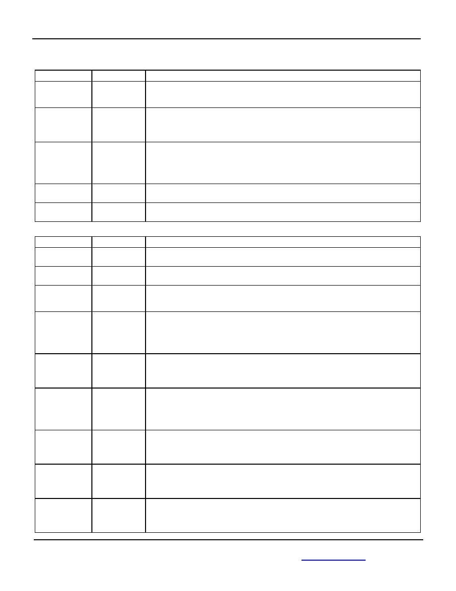
Pin Description
Power
Pin Number
Pin Name
Pin Function
1
VCCA
Analog PLL Power Pin: Connects to “quiet” 3.3V supply. 3.3V power pins are not internally
connected on the die, and must be connected together on the PCB. Bypass with
0.1F//0.01F low ESR capacitors and place as close to the VCCA pin as possible.
3
VCCD
Digital Logic Core Power Pin: VCCD connects to a 3.3V supply. Power pins are not internally
connected on the die, and must be connected together on the PCB. Bypass with
0.1F//0.01F low ESR capacitors and place bypass capacitors as close to the VCCD pin as
possible.
14, 27, 30, 36
VCCO
LVDS and LVPECL Output Driver Power Pins: The outputs can be powered from a 2.5V
supply or 3.3V supply. Connect all VCCO pins to the same power supply: 3.3V ±10% or 2.5V
±5%. Power pins are not internally connected on the die, and must be connected together on
the PCB. Bypass with 0.1F//0.01F low ESR capacitor and place as close to the VCCO pin
as possible.
10
GNDA
PLL Ground: Connect to “quiet” ground. GNDA and GND are not internally connected on the
die, and must be connected on the PCB.
11, 21, 22
GND,
Exposed Pad
Ground: GND pins and exposed pad must both be connected to the most negative potential
of the chip ground.
Control and Configuration
Pin Number
Pin Name
Pin Function
43
LR
Analog Input/Output: Provides the reference voltage for the PLL loop filter and is used with the
LF pin. See "External Loop Filter Considerations" for recommended loop filter values.
44
LF
Analog Input/Output: Provides the loop filter node for the PLL. See “External Loop Filter
Considerations” for loop filter values.
2, 4
RSEL1, RSEL0
TTL/CMOS Reference Input Pre-scaler. The two-bit input pre-scaler divides the input
reference frequency by /1, /2, /4, or /8. RSEL0 is the LSB bit. See "Reference Input Divider
Select Table," for proper decoding. The threshold voltage VTH = VCC/2. Internal 25k pull-up.
7
INSEL
TTL/CMOS Input Select Control. Selects either XTAL or Reference (RFCK) input. Internal
25k pull-up. The default is logic HIGH, and selects the XTAL input. The threshold voltage VTH
= VCC/2.
Logic HIGH: XTAL Select
Logic LOW: Reference Input Select
23
LSEL
TTL/CMOS input select control signal for the LVDS LOUT0-LOUT2 outputs. LSEL and LEN
are used to decode the selection and the post divider of the LVDS output bank. LSEL includes
an internal 25k pull-up. See “LVDS Output and Frequency Select Table” for proper decoding.
The threshold voltage VTH = VCC/2.
24
LEN
TTL/CMOS Input Enable Pin. Used to control the LOUT0-LOUT2 outputs and acts as a
frequency select pin. LEN and LSEL are used to decode the selection and the post divider of
the LVDS output bank. See the “LVDS Output and Frequency Select Table” for proper
decoding. LEN includes an internal 25k pull-up. When disabled, LOUT0-LOUT2 outputs are
LOW, and the complimentary outputs are HIGH. The threshold voltage VTH = VCC/2.
17
19
39
41
PSEL0
PSEL1
PSEL2
PSEL3
TTL/CMOS input select control signals for the PECL POUT0-POUT3 outputs. PSELx and
PENx are used together to decode the selection and post divider of the PECL outputs. PSELx
pins include an internal 25k pull-up. The threshold voltage VTH = VCC/2. See "PECL Output
Frequency and Select Table" for proper decoding.
18
20
40
42
PEN0
PEN1
PEN2
PEN3
TTL/CMOS input enable pin. Used to control the POUT0-PECL2 outputs and acts as a
frequency select pins. PENx and PSELx are used together; see the “PECL Output and
Frequency Select Table” for proper decoding. PENx includes an internal 25k pull-up. When
disabled, PECL0-PECL2 outputs are LOW. The threshold voltage VTH = VCC/2.
33
SYNC
TTL/CMOS output bank synchronization control. Internal 25k pull-up. The default state is
HIGH. After any bank has been programmed, all PECL and LVDS outputs are synchronized
when the SYNC control pin is toggled with a HIGH-LOW-HIGH transition. See
“Synchronization” section for details. The threshold voltage VTH = VCC/2.
相关PDF资料 |
PDF描述 |
|---|---|
| VI-B7Z-MX-F4 | CONVERTER MOD DC/DC 2V 30W |
| 74ACT139PC | IC DECODER/DEMUX 2OF4 16-DIP |
| VI-B7X-MY-F1 | CONVERTER MOD DC/DC 5.2V 50W |
| V28A24H200B3 | CONVERTER MOD DC/DC 24V 200W |
| SY89426JY TR | IC SYNTHESIZER CLK SONET 28-PLCC |
相关代理商/技术参数 |
参数描述 |
|---|---|
| SY89538L | 制造商:MICREL 制造商全称:Micrel Semiconductor 功能描述:3.3V, Precision LVPECL and LVDS Programmable Multiple Output Bank Clock Synthesizer and Fanout Buffer with Zero Delay |
| SY89538L_06 | 制造商:MICREL 制造商全称:Micrel Semiconductor 功能描述:3.3V, Precision LVPECL and LVDS Programmable Multiple Output Bank Clock Synthesizer and Fanout Buffer with Zero Delay |
| SY89538L_08 | 制造商:MICREL 制造商全称:Micrel Semiconductor 功能描述:3.3V, Precision LVPECL and LVDS Programmable Multiple Output Bank Clock Synthesizer |
| SY89538LHG | 功能描述:IC SYNTH/BUFF LVPECL/LVDS 64TQFP RoHS:是 类别:集成电路 (IC) >> 时钟/计时 - 时钟发生器,PLL,频率合成器 系列:Precision Edge® 产品变化通告:Product Discontinuation 04/May/2011 标准包装:96 系列:- 类型:时钟倍频器,零延迟缓冲器 PLL:带旁路 输入:LVTTL 输出:LVTTL 电路数:1 比率 - 输入:输出:1:8 差分 - 输入:输出:无/无 频率 - 最大:133.3MHz 除法器/乘法器:是/无 电源电压:3 V ~ 3.6 V 工作温度:0°C ~ 70°C 安装类型:表面贴装 封装/外壳:16-TSSOP(0.173",4.40mm 宽) 供应商设备封装:16-TSSOP 包装:管件 其它名称:23S08-5HPGG |
| SY89538LHG TR | 功能描述:IC SYNTHESIZR LVPECL/LVDS 64TQFP RoHS:是 类别:集成电路 (IC) >> 时钟/计时 - 时钟发生器,PLL,频率合成器 系列:Precision Edge® 产品变化通告:Product Discontinuation 04/May/2011 标准包装:96 系列:- 类型:时钟倍频器,零延迟缓冲器 PLL:带旁路 输入:LVTTL 输出:LVTTL 电路数:1 比率 - 输入:输出:1:8 差分 - 输入:输出:无/无 频率 - 最大:133.3MHz 除法器/乘法器:是/无 电源电压:3 V ~ 3.6 V 工作温度:0°C ~ 70°C 安装类型:表面贴装 封装/外壳:16-TSSOP(0.173",4.40mm 宽) 供应商设备封装:16-TSSOP 包装:管件 其它名称:23S08-5HPGG |
发布紧急采购,3分钟左右您将得到回复。