- 您现在的位置:买卖IC网 > PDF目录98158 > TAS3202PAGR (TEXAS INSTRUMENTS INC) SPECIALTY CONSUMER CIRCUIT, PQFP64 PDF资料下载
参数资料
| 型号: | TAS3202PAGR |
| 厂商: | TEXAS INSTRUMENTS INC |
| 元件分类: | 消费家电 |
| 英文描述: | SPECIALTY CONSUMER CIRCUIT, PQFP64 |
| 封装: | GREEN, PLASTIC, TQFP-64 |
| 文件页数: | 18/66页 |
| 文件大小: | 817K |
| 代理商: | TAS3202PAGR |
第1页第2页第3页第4页第5页第6页第7页第8页第9页第10页第11页第12页第13页第14页第15页第16页第17页当前第18页第19页第20页第21页第22页第23页第24页第25页第26页第27页第28页第29页第30页第31页第32页第33页第34页第35页第36页第37页第38页第39页第40页第41页第42页第43页第44页第45页第46页第47页第48页第49页第50页第51页第52页第53页第54页第55页第56页第57页第58页第59页第60页第61页第62页第63页第64页第65页第66页
D7
D0 ACK
Stop
Condition
Acknowledge
I CDevice Addressand
2
Read/WriteBit
Subaddress
LastDataByte
A6
A5
A1
A0 R/W ACK A7
A5
A1
A0
ACK D7
ACK
Start
Condition
Acknowledge
FirstDataByte
A4
A3
A6
OtherDataBytes
ACK
Acknowledge
D0
D7
D0
T0036-02
A6
A0
ACK
Acknowledge
I CDevice Addressand
Read/WriteBit
2
R/W
A6
A0
R/W ACK
A0 ACK
D7
D0
ACK
Start
Condition
Stop
Condition
Acknowledge
LastDataByte
ACK
FirstDataByte
RepeatStart
Condition
Not
Acknowledge
I CDevice Addressand
Read/WriteBit
2
Subaddress
OtherDataBytes
A7
A6
A5
D7
D0 ACK
Acknowledge
D7
D0
T0036-04
www.ti.com
SLES208B – JUNE 2009 – REVISED MARCH 2011
Sequential I2C Transactions
The TAS3202 also supports sequential I2C addressing. For write transactions, if a subaddress is issued
followed by data for that subaddress and the 15 subaddresses that follow, a sequential I2C write
transaction has taken place, and the data for all 16 subaddresses is successfully received by the
TAS3202. For I2C sequential write transactions, the subaddress then serves as the start address and the
amount of data subsequently transmitted, before a stop or start is transmitted, determines how many
subaddresses are written to. As was true for random addressing, sequential addressing requires that a
complete set of data be transmitted. If only a partial set of data is written to the last subaddress, the data
for the last subaddress is discarded. However, all other data written is accepted; just the incomplete data
is discarded.
Sequential read transactions do not have restrictions on outputting only complete subaddress data sets.
If the master does not issue enough data-received acknowledges to receive all the data for a given
subaddress, the master device simply does not receive all the data.
If the master device issues more data-received acknowledges than required to receive the data for a given
subaddress, the master device simply receives complete or partial sets of data, depending on how many
data-received acknowledges are issued from the subaddress(es) that follow. I2C read transactions, both
sequential and random, can impose I2C clock stretching..
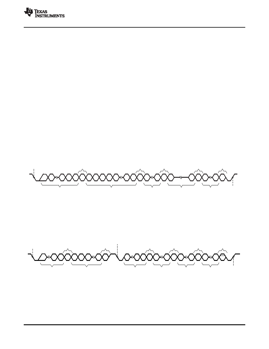
6.3.1
Multiple-Byte Write
Multiple data bytes are transmitted by the master device to slave as shown in Figure 6-4. After receiving
each data byte, the TAS3202 responds with an acknowledge bit.
Figure 6-4. Multiple-Byte Write Transfer
6.3.2
Multiple-Byte Read
Multiple data bytes are transmitted by the TAS3202 to the master device as shown in Figure 6-5. Except
for the last data byte, the master device responds with an acknowledge bit after receiving each data byte.
Figure 6-5. Multiple-Byte Read Transfer
6.4
I
2C Master-Mode Device Initialization
I2C master-mode operation is enabled following a reset or power-on reset. Master-mode I2C transactions
do not start until the I2C bus is idle.
Copyright 2009–2011, Texas Instruments Incorporated
Microprocessor Controller
25
Product Folder Link(s): TAS3202
相关PDF资料 |
PDF描述 |
|---|---|
| TAS3202PAG | SPECIALTY CONSUMER CIRCUIT, PQFP64 |
| TAS3204PAGR | SPECIALTY CONSUMER CIRCUIT, PQFP64 |
| TAS3204PAG | SPECIALTY CONSUMER CIRCUIT, PQFP64 |
| TAS3218IPZPR | SPECIALTY CONSUMER CIRCUIT, PQFP100 |
| TAS3218IPZP | SPECIALTY CONSUMER CIRCUIT, PQFP100 |
相关代理商/技术参数 |
参数描述 |
|---|---|
| TAS3204 | 制造商:TI 制造商全称:Texas Instruments 功能描述:AUDIO DSP WITH ANALOG INTERFACE |
| TAS3204EVM | 功能描述:音频 IC 开发工具 TAS3204EVM Eval Mod RoHS:否 制造商:Texas Instruments 产品:Evaluation Kits 类型:Audio Amplifiers 工具用于评估:TAS5614L 工作电源电压:12 V to 38 V |
| TAS3204EVM-LC | 制造商:Texas Instruments 功能描述:TAS3204EVM EVALUATION MODULE - Boxed Product (Development Kits) |
| TAS3204PAG | 功能描述:音频 DSP Hi Perf Dual Core DSP/MCU Aud Proc RoHS:否 制造商:Texas Instruments 工作电源电压: 电源电流: 工作温度范围: 安装风格: 封装 / 箱体: 封装:Tube |
| TAS3204PAGR | 功能描述:音频 DSP Hi Perf Dual Core DSP/MCU Aud Proc RoHS:否 制造商:Texas Instruments 工作电源电压: 电源电流: 工作温度范围: 安装风格: 封装 / 箱体: 封装:Tube |
发布紧急采购,3分钟左右您将得到回复。