- 您现在的位置:买卖IC网 > PDF目录98165 > TB1230AN SPECIALTY CONSUMER CIRCUIT, PDIP56 PDF资料下载
参数资料
| 型号: | TB1230AN |
| 元件分类: | 消费家电 |
| 英文描述: | SPECIALTY CONSUMER CIRCUIT, PDIP56 |
| 封装: | 0.600 INCH, 1.78 MM PITCH, SHRINK, PLASTIC, DIP-56 |
| 文件页数: | 69/90页 |
| 文件大小: | 1333K |
| 代理商: | TB1230AN |
第1页第2页第3页第4页第5页第6页第7页第8页第9页第10页第11页第12页第13页第14页第15页第16页第17页第18页第19页第20页第21页第22页第23页第24页第25页第26页第27页第28页第29页第30页第31页第32页第33页第34页第35页第36页第37页第38页第39页第40页第41页第42页第43页第44页第45页第46页第47页第48页第49页第50页第51页第52页第53页第54页第55页第56页第57页第58页第59页第60页第61页第62页第63页第64页第65页第66页第67页第68页当前第69页第70页第71页第72页第73页第74页第75页第76页第77页第78页第79页第80页第81页第82页第83页第84页第85页第86页第87页第88页第89页第90页
TB1230AN
2001-09-04
71
TEST CONDITION (Unless otherwise specified : H, RGB VCC = 9V ; VDD, Fsc VDD, Y / C VCC = 5V ; Ta = 25±3°C ; BUS = preset value)
SW MODE
SUB-ADDRESS & BUS DATA
NOTE
ITEM
S21
S22
S31
S33
S34
S51
―
01H
05H
―
MEASURING METHOD
T15
Brightness Control
Characteristic
B
A
―
FFH
00H
10H
―
(1)
Short circuit pin 31 (Y IN), pin 33 (B-Y IN) and pin 34 (R-Y IN)
in AC coupling.
(2)
Input 0.3V synchronizing signal to pin 51 (Sync IN).
(3)
Set bus data so that R, G, B cut off data are set at center
value.
T16
Brightness Center
Voltage
↑
―
80H
↑
―
(4)
Connect pin 21 (Digital Ys) and pin 22 (Analog Ys) to ground.
(5)
While changing bus data on brightness from maximum to
minimum, measure video voltage of pin 13 (G OUT) to find
maximum and minimum voltages (max : Vbrmx, min : Vbrmn).
(6)
With bus data on brightness set at center value, measure
video voltage of pin 13 (G OUT) (Vbcnt).
T17
Brightness Data
Sensitivity
↑
―
(7)
On the conditon that bus data with which Vbrmx is obtained in
measurement of the above step 5 is Dbrmx and bus data with
which Vbrmn is obtained in measurement of the above step 5 is
Dbrmn, calculate sensitivity of brightness data (Vbrt).
Vbrt = (Vbrmxg Vbrmng) / (Dbrmxg Dbrmng)
T18
RGB Output
Voltage Axes
Difference
↑
―
(1)
In the same manner as the Note T16, measure video voltage
of pin 12 (B OUT) with bus data on brightness set at center
value.
(2)
Find maximum axes difference in the brightness center
voltage.
T19
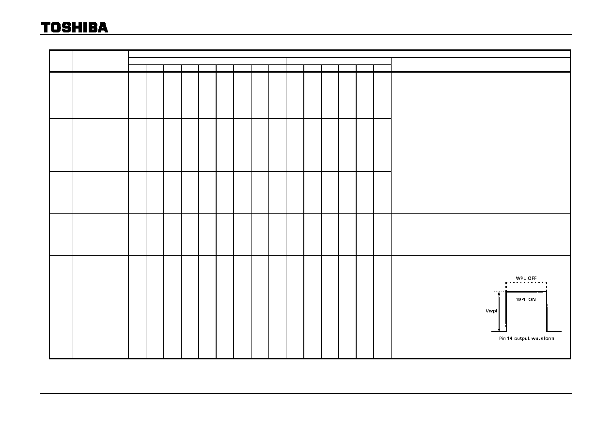
White Peak Limit
Level
↑
―
00H
1FH
―
(1)
Set bus data so that contrast and Y sub contrast are
maximum and brightness is minimum.
(2)
Input TG7 sine wave
signal whose frequency is
100kHz and amplitude in
video period is 0.9V to pin
31 (Y IN).
(3)
Connect pin 21 (Digital Ys)
and pin 22 (Analog Ys) to
ground.
(4)
While turning on / off WPL
with bus, measure video
amplitude of pin 14 (R OUT) with WPL being activated (Vwpl).
相关PDF资料 |
PDF描述 |
|---|---|
| TB1231BN | SPECIALTY CONSUMER CIRCUIT, PDIP56 |
| TB1231CN | SPECIALTY CONSUMER CIRCUIT, PDIP56 |
| TB1231N | SPECIALTY CONSUMER CIRCUIT, PDIP56 |
| TB1238BN | SPECIALTY CONSUMER CIRCUIT, PDIP56 |
| TB1238N | SPECIALTY CONSUMER CIRCUIT, PDIP56 |
相关代理商/技术参数 |
参数描述 |
|---|---|
| TB1231AN | 制造商:TOSHIBA 制造商全称:Toshiba Semiconductor 功能描述:PAL/NTSC 1CHIP (IF + VCD PROCESSOR) IC |
| TB1231CN | 制造商:TOSHIBA 制造商全称:Toshiba Semiconductor 功能描述:PAL/NTSC 1CHIP (IF+VCD PROCESSOR) IC |
| TB1238BN | 制造商:TOSHIBA 制造商全称:Toshiba Semiconductor 功能描述:PAL/NTSC 1CHIP (IF + VCD PROCESSOR) IC |
| TB1238N | 制造商:TOSHIBA 制造商全称:Toshiba Semiconductor 功能描述:PAL/NTSC 1CHIP (IF+VCD PROCESSOR) IC |
| TB1239BF | 制造商:TOSHIBA 制造商全称:Toshiba Semiconductor 功能描述:Bi-CMOS Integrated Circuit Silicon Monolithic |
发布紧急采购,3分钟左右您将得到回复。