- 您现在的位置:买卖IC网 > PDF目录98170 > TC642BEOA713 BRUSHLESS DC MOTOR CONTROLLER, PDSO8 PDF资料下载
参数资料
| 型号: | TC642BEOA713 |
| 元件分类: | 运动控制电子 |
| 英文描述: | BRUSHLESS DC MOTOR CONTROLLER, PDSO8 |
| 封装: | 0.150 INCH, PLASTIC, SOIC-8 |
| 文件页数: | 4/34页 |
| 文件大小: | 683K |
| 代理商: | TC642BEOA713 |
第1页第2页第3页当前第4页第5页第6页第7页第8页第9页第10页第11页第12页第13页第14页第15页第16页第17页第18页第19页第20页第21页第22页第23页第24页第25页第26页第27页第28页第29页第30页第31页第32页第33页第34页
TC642B/TC647B
DS21756B-page 12
2003 Microchip Technology Inc.
By modulating the voltage applied to the gate of the
MOSFET (QDRIVE), the voltage that is applied to the
fan is also modulated. When the VOUT pulse is high, the
gate of the MOSFET is turned on, pulling the voltage at
the drain of QDRIVE to zero volts. This places the full
12V across the fan for the ton period of the pulse. When
the duty cycle of the drive pulse is 100% (full on,
ton = t), the fan will run at full speed. As the duty cycle
is decreased (pulse on time “ton” is lowered), the fan
will slow down proportionally. With the TC642B and
TC647B devices, the duty cycle is controlled by either
the VIN or VMIN input, with the higher voltage setting the
duty cycle. This is described in more detail in Section
5.5, “Output Drive Device Selection”.
4.3
Fan Start-up
Often overlooked in fan speed control is the actual start-
up control period. When starting a fan from a non-oper-
ating condition (fan speed is zero revolutions per minute
(RPM)), the desired PWM duty cycle or average fan
voltage can not be applied immediately. Since the fan is
at a rest position, the fan’s inertia must be overcome to
get it started. The best way to accomplish this is to apply
the full rated voltage to the fan for a minimum of one
second. This will ensure that in all operating environ-
ments, the fan will start and operate properly. An exam-
ple of the start-up timing is shown in Figure 1-1.
A key feature of the TC642B/TC647B device is the
start-up timer. When power is first applied to the device,
(when the device is brought out of the shutdown mode
of operation) the VOUT output will go to a high state for
32 PWM cycles (one second for CF = 1 F). This will
drive the fan to full speed for this time-frame.
During the start-up period, the SENSE pin is being
monitored for fan pulses. If pulses are detected during
this period, the fan speed controller will then move to
PWM operation (see Section 4.5, “Minimum Fan
Speed”, for more details on operation when coming out
of start-up). If pulses are not detected during the start-
up period, the start-up timer is activated again. If pulses
are not detected at the SENSE pin during this addi-
tional start-up period, the FAULT output will go low to
indicate that a fan fault condition has occurred. See
Section 4.7, “FAULT Output”, for more details.
4.4
PWM Frequency & Duty Cycle Control
(CF & VIN Pins)
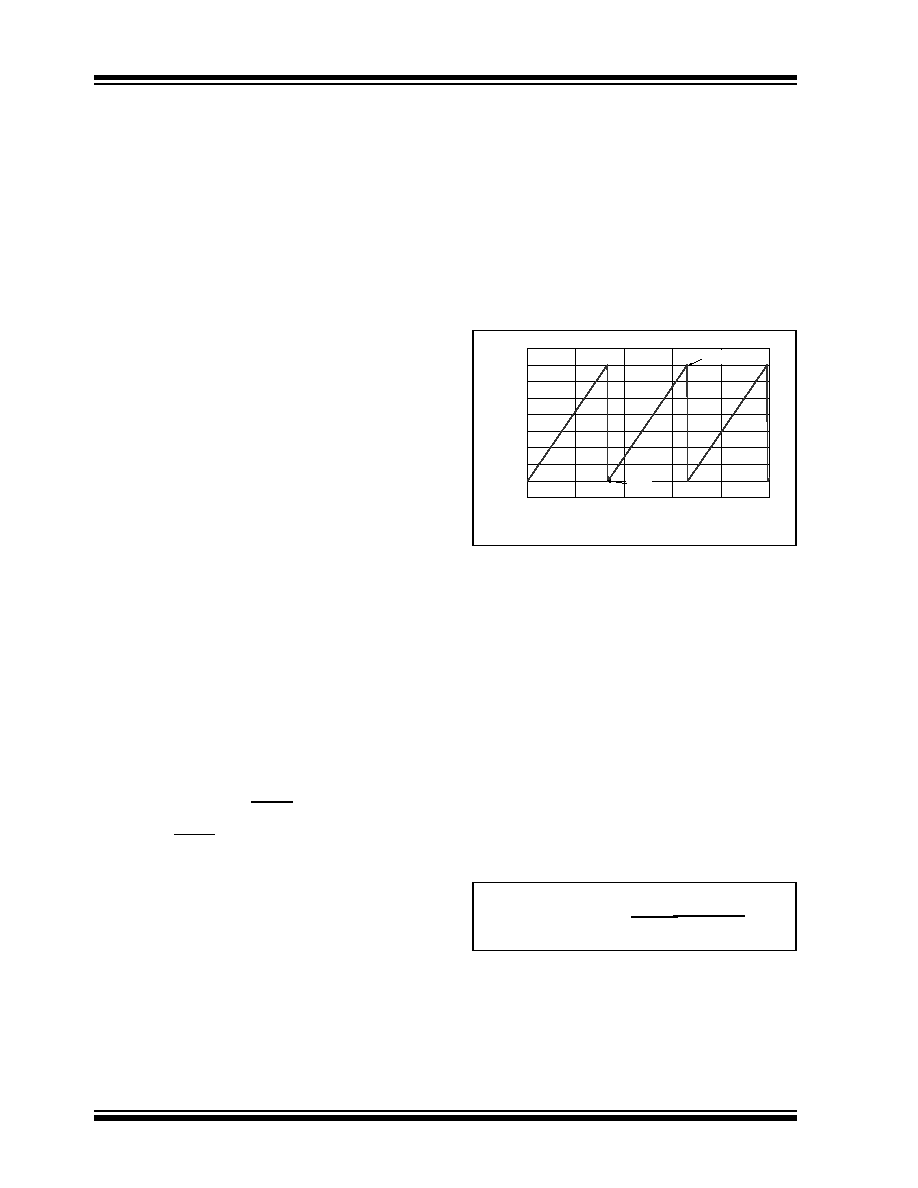
The frequency of the PWM pulse train is controlled by
the CF pin. By attaching a capacitor to the CF pin, the
frequency of the PWM pulse train can be set to the
desired value. The typical PWM frequency for a 1.0
F
capacitor is 30 Hz. The frequency can be adjusted by
raising or lowering the value of the capacitor. The CF
pin functions as a ramp generator. The voltage at this
pin will ramp from 1.20V to 2.60V (typically) as a saw-
tooth waveform. An example of this is shown in
FIGURE 4-3:
CF Pin Voltage.
The duty cycle of the PWM output is controlled by the
voltage at the VIN input pin (or the VMIN voltage, which-
ever is greater). The duty cycle of the PWM output is
produced by comparing the voltage at the VIN pin to the
voltage ramp at the CF pin. When the voltage at the VIN
pin is 1.20V, the duty cycle will be 0%. When the volt-
age at the VIN pin is 2.60V, the PWM duty cycle will be
100% (these are both typical values). The VIN to PWM
duty cycle relationship is shown in Figure 4-4.
The lower value of 1.20V is referred to as VCMIN and
the 2.60V threshold is referred to as VCMAX. A calcula-
tion for duty cycle is shown in the equation below. The
voltage range between VCMIN and VCMAX is character-
ized as VCSPAN and has a typical value of 1.4V with
minimum and maximum values of 1.3V and 1.5V,
respectively.
EQUATION
PWM DUTY CYCLE
1.0
1.2
1.4
1.6
1.8
2.0
2.2
2.4
2.6
2.8
0
20
406080
100
Time (msec)
C
FVoltage
(V)
CF = 1 F
VCMAX
VCMIN
Duty Cycle (%) =
VCMAX - VCMIN
(VIN - VCMIN) * 100
相关PDF资料 |
PDF描述 |
|---|---|
| TC647BEUA | BRUSHLESS DC MOTOR CONTROLLER, PDSO8 |
| TC642BEOA | BRUSHLESS DC MOTOR CONTROLLER, PDSO8 |
| TC647EOATR | BRUSHLESS DC MOTOR CONTROLLER, PDSO8 |
| TC647VUATR | BRUSHLESS DC MOTOR CONTROLLER, PDSO8 |
| TC647VOART | BRUSHLESS DC MOTOR CONTROLLER, PDSO8 |
相关代理商/技术参数 |
参数描述 |
|---|---|
| TC642BEOAG | 制造商:Microchip Technology 功能描述:Fan Control Demo Board |
| TC642BEOATR | 制造商:MICROCHIP 制造商全称:Microchip Technology 功能描述:PWM Fan Speed Controllers With Minimum Fan Speed, Fan Restart and FanSense⑩ Technology for Fault Detection |
| TC642BEPA | 功能描述:马达/运动/点火控制器和驱动器 w/Rstrt & Flt Dtct RoHS:否 制造商:STMicroelectronics 产品:Stepper Motor Controllers / Drivers 类型:2 Phase Stepper Motor Driver 工作电源电压:8 V to 45 V 电源电流:0.5 mA 工作温度:- 25 C to + 125 C 安装风格:SMD/SMT 封装 / 箱体:HTSSOP-28 封装:Tube |
| TC642BEPA713 | 制造商:MICROCHIP 制造商全称:Microchip Technology 功能描述:PWM Fan Speed Controllers With Minimum Fan Speed, Fan Restart and FanSense⑩ Technology for Fault Detection |
| TC642BEPATR | 制造商:MICROCHIP 制造商全称:Microchip Technology 功能描述:PWM Fan Speed Controllers With Minimum Fan Speed, Fan Restart and FanSense⑩ Technology for Fault Detection |
发布紧急采购,3分钟左右您将得到回复。