- 您现在的位置:买卖IC网 > PDF目录69480 > TC642EUA BRUSHLESS DC MOTOR CONTROLLER, PDSO8 PDF资料下载
参数资料
| 型号: | TC642EUA |
| 元件分类: | 运动控制电子 |
| 英文描述: | BRUSHLESS DC MOTOR CONTROLLER, PDSO8 |
| 封装: | PLASTIC, MSOP-8 |
| 文件页数: | 4/28页 |
| 文件大小: | 485K |
| 代理商: | TC642EUA |
第1页第2页第3页当前第4页第5页第6页第7页第8页第9页第10页第11页第12页第13页第14页第15页第16页第17页第18页第19页第20页第21页第22页第23页第24页第25页第26页第27页第28页
TC642
DS21444C-page 12
2002 Microchip Technology Inc.
on the nominal operating current of the fan. Note that
the current draw specified by the fan manufacturer may
be a worst-case rating for near-stall conditions and may
not be the fan’s nominal operating current. The values
in Table 5-1 refer to actual average operating current. If
the fan current falls between two of the values listed,
use the higher resistor value. The end result of employ-
ing Table 5-1 is that the signal developed across the
sense resistor is approximately 450 mV in amplitude.
TABLE 5-1:
RSENSE VS. FAN CURRENT
5.5
Output Drive Transistor Selection
The TC642 is designed to drive an external transistor
or MOSFET for modulating power to the fan. This is
of 5 mA and a minimum sink current of 1 mA. Bipolar
transistors or MOSFETs may be used as the power
switching element, as shown in Figure 5-7. When high
current gain is needed to drive larger fans, two transis-
tors may be used in a Darlington configuration. Three
possible circuit topologies are shown in Figure 5-7: (a)
shows a single NPN transistor used as the switching
element; (b) illustrates the Darlington pair; and (c)
shows an N-channel MOSFET.
One major advantage of the TC642’s PWM control
scheme versus linear speed control is that the power
dissipation in the pass element is kept very low. Gener-
ally, low cost devices in very small packages, such as
TO-92 or SOT, can be used effectively. For fans with
nominal operating currents of no more than 200 mA, a
single transistor usually suffices. Above 200 mA, the
Darlington or MOSFET solution is recommended. For
the fan sensing function to work correctly, it is impera-
tive that the pass transistor be fully saturated when
“on”.
Table 5-2 gives examples of some commonly available
transistors and MOSFETs. This table should be used
as a guide only since there are many transistors and
MOSFETs which will work just as well as those listed.
The critical issues when choosing a device to use as
Q1 are: (1) the breakdown voltage (V(BR)CEO or VDS
(MOSFET)) must be large enough to withstand the
highest voltage applied to the fan (Note: This will occur
when the fan is off); (2) 5 mA of base drive current must
be enough to saturate the transistor when conducting
the full fan current (transistor must have sufficient
gain); (3) the VOUT voltage must be high enough to suf-
ficiently drive the gate of the MOSFET to minimize the
RDS(on) of the device; (4) rated fan current draw must
be within the transistor's/MOSFET's current handling
capability; and (5) power dissipation must be kept
within the limits of the chosen device.
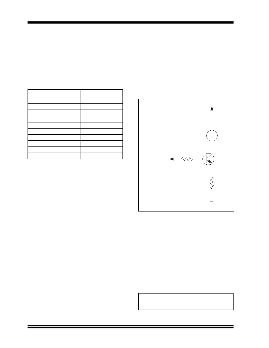
A base-current limiting resistor is required with bipolar
transistors (Figure 5-6).
FIGURE 5-6:
Circuit For Determining
RBASE.
The correct value for this resistor can be determined as
follows:
VOH
= VRSENSE + VBE(SAT) + VRBASE
VRSENSE = IFAN x RSENSE
VRBASE
= RBASE x IBASE
IBASE
= IFAN / hFE
cal Characteristics”; VBE(SAT) is given in the chosen
transistor’s data sheet. It is now possible to solve for
RBASE.
EQUATION
Nominal Fan Current (mA)
RSENSE ()
50
9.1
100
4.7
150
3.0
200
2.4
250
2.0
300
1.8
350
1.5
400
1.3
450
1.2
500
1.0
Q1
GND
VDD
RSENSE
RBASE
VOH = 80% VDD
+ V
RBASE
–
+ V
BE(SAT)
–
+
VR
SENSE
–
Fan
RBASE =
VOH - VBE(SAT) - VRSENSE
IBASE
相关PDF资料 |
PDF描述 |
|---|---|
| TC642EUA713 | BRUSHLESS DC MOTOR CONTROLLER, PDSO8 |
| TC642EOA713 | BRUSHLESS DC MOTOR CONTROLLER, PDSO8 |
| TC646EOA | BRUSHLESS DC MOTOR CONTROLLER, PDSO8 |
| TC646VUA | BRUSHLESS DC MOTOR CONTROLLER, PDSO8 |
| TC646VOA713G | BRUSHLESS DC MOTOR CONTROLLER, PDSO8 |
相关代理商/技术参数 |
参数描述 |
|---|---|
| TC642EUA713 | 功能描述:马达/运动/点火控制器和驱动器 w/Fault Dtct RoHS:否 制造商:STMicroelectronics 产品:Stepper Motor Controllers / Drivers 类型:2 Phase Stepper Motor Driver 工作电源电压:8 V to 45 V 电源电流:0.5 mA 工作温度:- 25 C to + 125 C 安装风格:SMD/SMT 封装 / 箱体:HTSSOP-28 封装:Tube |
| TC642EV | 功能描述:电源管理IC开发工具 For TC642/6/7/8/9 RoHS:否 制造商:Maxim Integrated 产品:Evaluation Kits 类型:Battery Management 工具用于评估:MAX17710GB 输入电压: 输出电压:1.8 V |
| TC642EV | 制造商:Microchip Technology Inc 功能描述:Tools Development kit For Use |
| TC642VOA | 功能描述:马达/运动/点火控制器和驱动器 w/Fault Dtct RoHS:否 制造商:STMicroelectronics 产品:Stepper Motor Controllers / Drivers 类型:2 Phase Stepper Motor Driver 工作电源电压:8 V to 45 V 电源电流:0.5 mA 工作温度:- 25 C to + 125 C 安装风格:SMD/SMT 封装 / 箱体:HTSSOP-28 封装:Tube |
| TC642VOA713 | 功能描述:马达/运动/点火控制器和驱动器 w/Fault Dtct RoHS:否 制造商:STMicroelectronics 产品:Stepper Motor Controllers / Drivers 类型:2 Phase Stepper Motor Driver 工作电源电压:8 V to 45 V 电源电流:0.5 mA 工作温度:- 25 C to + 125 C 安装风格:SMD/SMT 封装 / 箱体:HTSSOP-28 封装:Tube |
发布紧急采购,3分钟左右您将得到回复。