- 您现在的位置:买卖IC网 > PDF目录196353 > TCA8418EYFPR (TEXAS INSTRUMENTS INC) SPECIALTY ANALOG CIRCUIT, BGA25 PDF资料下载
参数资料
| 型号: | TCA8418EYFPR |
| 厂商: | TEXAS INSTRUMENTS INC |
| 元件分类: | 模拟信号调理 |
| 英文描述: | SPECIALTY ANALOG CIRCUIT, BGA25 |
| 封装: | 2 X 2 MM, 0.40 MM PITCH, DSBGA-25 |
| 文件页数: | 9/31页 |
| 文件大小: | 400K |
| 代理商: | TCA8418EYFPR |
第1页第2页第3页第4页第5页第6页第7页第8页当前第9页第10页第11页第12页第13页第14页第15页第16页第17页第18页第19页第20页第21页第22页第23页第24页第25页第26页第27页第28页第29页第30页第31页
www.ti.com
SCPS222B – MAY 2010 – REVISED SEPTEMBER 2010
BIT
NAME
DESCRIPTION
2
KEC2
Key event count, Bit 2
1
KEC1
Key event count, Bit 1
0
KEC0
Key event count, Bit 0
KEC[3:0]: indicates how many registers have values in it. For example, KS(0000) = 0 events, KS(0001) = 1 event
and KS(1010) = 10 events. As interrupts happen (press or release), the count increases accordingly.
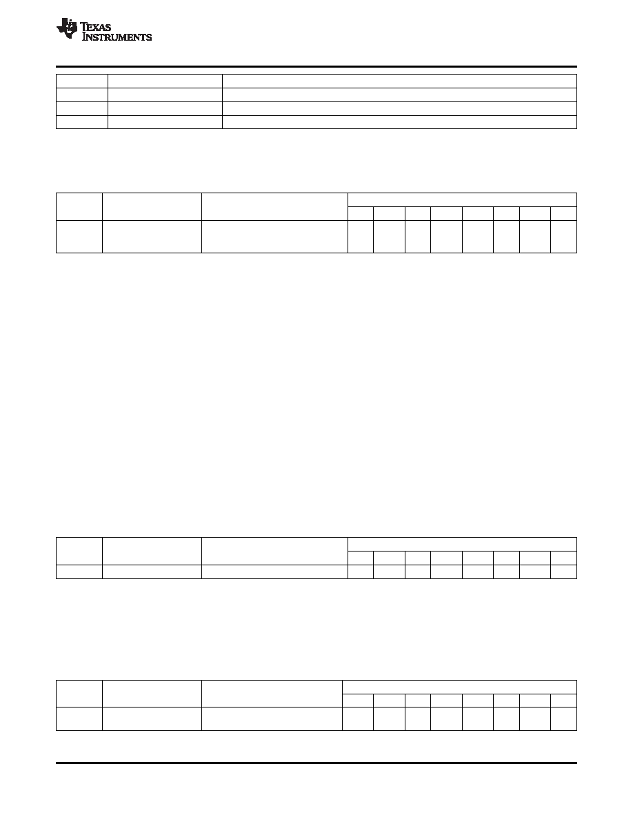
Key Event Registers (FIFO), KEY_EVENT_A–J (Address 0×04–0×0D)
BIT
ADDRESS
REGISTER NAME(1)
REGISTER DESCRIPTION
7
6
5
4
3
2
1
0
KEA
KEA6
KEA4
KEA3
KEA1
0×04
KEY_EVENT_A
Key event register A
7
5
2
0
(1)
Only KEY_EVENT_A register is shown
These registers – KEY_EVENT_A-J – function as a FIFO stack which can store up to 10 key presses and
releases. The user first checks the INT_STAT register to see if there are any interrupts. If so, then the Key Lock
and Event Counter Register (KEY_LCK_EC, register 0x03) is read to see how many interrupts are stored. The
INT_STAT register is then read again to ensure no new events have come in. The KEY_EVENT_A register is
then read as many times as there are interrupts. Each time a read happens, the count in the KEY_LCK_EC
register reduces by 1. The data in the FIFO also moves down the stack by 1 too (from KEY_EVENT_J to
KEY_EVENT_A). Once all events have been read, the key event count is at 0 and then KE_INT bit can be
cleared by writing a ‘1’ to it.
In the KEY_EVENT_A register, KEA[6:0] indicates the key # pressed or released. A value of 0 to 80 indicate
which key has been pressed or released in a keypad matrix. Values of 97 to 114 are for GPI events.
Bit 7 or KEA[7] indicate if a key press or key release has happened. A ‘0’ means a key release happened. A ‘1’
means a key has been pressed (which can be cleared on a read).
For example, 3 key presses and 3 key releases are stored as 6 words in the FIFO. As each word is read, the
user knows if it is a key press or key release that occurred. Key presses such as CTRL+ALT+DEL are stored as
3 simultaneous key presses. Key presses and releases generate key event interrupts. The KE_INT bit and /INT
pin will not cleared until the FIFO is cleared of all events.
All registers can be read but for the purpose of the FIFO, the user should only read KEY_EVENT_A register.
Once all the events in the FIFO have been read, reading of KEY_EVENT_A register will yield a zero value.
Keypad Lock1 to Lock2 Timer Register, KP_LCK_TIMER (Address 0×0E)
BIT
ADDRESS
REGISTER NAME(1)
REGISTER DESCRIPTION
7
6
5
4
3
2
1
0
0×0E
KP_LCK_TIMER
Keypad lock 1 to lock 2 timer
KL7
KL6
KL5
KL4
KL3
KL2
KL1
KL0
(1)
Only KEY_EVENT_A register is shown
KL[2:0] are for the Lock1 to Lock2 timer
KL[7:3] are for the interrupt mask timer
The interrupt mask timer should be set for the time it takes for the LCD to dim or turn off.
Unlock1 and Unlock2 Registers, UNLOCK1/2 (Address o0×0F)
BIT
ADDRESS
REGISTER NAME(1)
REGISTER DESCRIPTION
7
6
5
4
3
2
1
0
UK1_
UK1
UK1_
UK1
UK1_
UK1
0×0F
Unlock1
Unlock key 1
7
6
_5
4
3
_2
1
_0
(1)
Only KEY_EVENT_A register is shown
Copyright 2010, Texas Instruments Incorporated
17
Product Folder Link(s): TCA8418E
相关PDF资料 |
PDF描述 |
|---|---|
| TCD2253D | SPECIALTY ANALOG CIRCUIT, CDIP22 |
| TCD4027036BC015000-12.75M | TCXO, CLIPPED SINE OUTPUT, 12.75 MHz |
| TCD4029055DK015000-10M | TCXO, CLIPPED SINE OUTPUT, 10 MHz |
| TCD4027036EH015000-12.75M | TCXO, CLIPPED SINE OUTPUT, 12.75 MHz |
| TCD4027036FG015000-12.75M | TCXO, CLIPPED SINE OUTPUT, 12.75 MHz |
相关代理商/技术参数 |
参数描述 |
|---|---|
| TCA8418EYFPR | 制造商:Texas Instruments 功能描述:IC I2C CONTROLLED KEYPAD SCAN 3.6V 25 |
| TCA8418RTWR | 功能描述:I2C 接口集成电路 Low-Vltg 16B I2C & SMBus I/O Expander RoHS:否 制造商:NXP Semiconductors 电源电压-最大:5.5 V 电源电压-最小:2.3 V 最大工作频率:400 KHz 最大工作温度:+ 85 C 封装 / 箱体:TSSOP-16 |
| TCA8418YFPR | 制造商:TI 制造商全称:Texas Instruments 功能描述:I2C CONTROLLED KEYPAD SCAN IC WITH INTEGRATED ESD PROTECTION |
| TCA8424 | 制造商:TI 制造商全称:Texas Instruments 功能描述:Check for Samples: TCA8424 |
| TCA8424EVM-038 | 功能描述:界面开发工具 TCA8424 EVAL MOD RoHS:否 制造商:Bourns 产品:Evaluation Boards 类型:RS-485 工具用于评估:ADM3485E 接口类型:RS-485 工作电源电压:3.3 V |
发布紧急采购,3分钟左右您将得到回复。