- 您现在的位置:买卖IC网 > PDF目录69485 > THMC41DR (TEXAS INSTRUMENTS INC) BRUSHLESS DC MOTOR CONTROLLER, 1.5 A, PDSO14 PDF资料下载
参数资料
| 型号: | THMC41DR |
| 厂商: | TEXAS INSTRUMENTS INC |
| 元件分类: | 运动控制电子 |
| 英文描述: | BRUSHLESS DC MOTOR CONTROLLER, 1.5 A, PDSO14 |
| 封装: | PLASTIC, SOP-14 |
| 文件页数: | 15/19页 |
| 文件大小: | 300K |
| 代理商: | THMC41DR |
THMC40, THMC41
VARIABLE SPEED 12-VDC BRUSHLESS FAN MOTOR DRIVERS
SLIS097 – MARCH 2000
5
POST OFFICE BOX 655303
DALLAS, TEXAS 75265
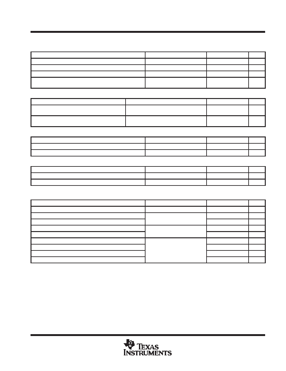
dc
electrical characteristics, VPWR = 12 V, TA = –30°C to 80°C (unless otherwise noted) (continued)
VPWM high-side PWM duty cycle adjust input
PARAMETER
TEST CONDITIONS
MIN
TYP
MAX
UNITS
IIB(PWM)
VPWM input bias current
VPWM = 0 V to 3 V
±1
A
VPWM (100%)
VPWM voltage equivalent to 100% duty cycle
2.3
V
VSLEEP
VPWM voltage threshold to engage sleep mode
0.6
0.7
V
VSTART
VPWM voltage threshold to disengage sleep
mode
0.8
0.9
V
thermal shutdown characteristics
PARAMETER
TEST CONDITIONS
MIN
TYP
MAX
UNITS
TTSD
VOUT, PHA, PHB global thermal shutdown
thresholds
Temperature increasing until outputs are off,
See Note 6
150
185
°C
THYST
Thermal shutdown hysteresis
After TTSD, temperature decreasing until out-
puts return to normal operation, See Note 6
15
°C
TACH Tachometer open-drain output (THMC40)
PARAMETER
TEST CONDITIONS
MIN
TYP
MAX
UNITS
ITACHLEAK
TACH high-level output leakage current
VTACH = 5 V
0.1
1
A
VOL
TACH low-level output voltage
ITACH = 5 mA
0.1
0.3
V
RD locked rotor detection open-drain output (THMC41)
PARAMETER
TEST CONDITIONS
MIN
TYP
MAX
UNITS
IRDLEAK
RD high-level output leakage current
VRD = 5 V, Locked rotor condition
0.1
1
A
VOL
RD low-level output voltage
IRD = 5 mA, No locked rotor
0.1
0.3
V
ac electrical characteristics, VPWR = 12 V, TA = –30°C to 80°C (unless otherwise noted)
PARAMETER
TEST CONDITIONS
MIN
TYP
MAX
UNITS
fPWM
High-side gate drive PWM frequency
COSC = 2200 pF
22.7
kHz
tRD
Locked rotor detect delay time
COSC = 2200 pF See Figure 9
1
s
tRETRY
Auto-restart delay time
COSC = 2200 pF, See Figure 9
8
s
tHALL
Hall zero-crossing deglitch time
See Figure 2
25
s
tDEAD(PHx) Dead time between phase commutations
See Figure 2
5
s
tf(OUT)
VOUT output fall time
25
ns
tr(OUT)
VOUT output rise time
RL = 20 , LL = 5 mH,
25
ns
tf(PHx)
PHA or PHB fall time
L
, L
,
See Note 6
1
s
tr(PHx)
PHA or PHB rise time
1
s
NOTE 6: Design targets only. Not tested in production.
相关PDF资料 |
PDF描述 |
|---|---|
| THMC40DR | BRUSHLESS DC MOTOR CONTROLLER, 1.5 A, PDSO14 |
| THMC45DGNR | BRUSHLESS DC MOTOR CONTROLLER, PDSO8 |
| THS7002CPWP | SPECIALTY ANALOG CIRCUIT, PDSO28 |
| THS7002IPWP | SPECIALTY ANALOG CIRCUIT, PDSO28 |
| THS7001IPWP | SPECIALTY ANALOG CIRCUIT, PDSO20 |
相关代理商/技术参数 |
参数描述 |
|---|---|
| THMC41SOPD | 制造商:TI 制造商全称:Texas Instruments 功能描述:VARIABLE SPEED 12-VDC BRUSHLESS FAN MOTOR DRIVERS |
| THMC45 | 制造商:TI 制造商全称:Texas Instruments 功能描述:5-V AND 3.3-V DC BRUSHLESS FAN MOTOR DRIVER WITH SINGLE WIRE CONTOL |
| THMC50 | 制造商:TI 制造商全称:Texas Instruments 功能描述:REMOTE/LOCAL TEMPERATURE MONITOR AND FAN CONTROLLER WITH SMBus INTERFACE |
| THMC50DBQR | 制造商:Rochester Electronics LLC 功能描述:- Bulk |
| THMC50SSOPDBQ | 制造商:TI 制造商全称:Texas Instruments 功能描述:REMOTE/LOCAL TEMPERATURE MONITOR AND FAN CONTROLLER WITH SMBus INTERFACE |
发布紧急采购,3分钟左右您将得到回复。