- 您现在的位置:买卖IC网 > PDF目录69485 > THMC41DR (TEXAS INSTRUMENTS INC) BRUSHLESS DC MOTOR CONTROLLER, 1.5 A, PDSO14 PDF资料下载
参数资料
| 型号: | THMC41DR |
| 厂商: | TEXAS INSTRUMENTS INC |
| 元件分类: | 运动控制电子 |
| 英文描述: | BRUSHLESS DC MOTOR CONTROLLER, 1.5 A, PDSO14 |
| 封装: | PLASTIC, SOP-14 |
| 文件页数: | 16/19页 |
| 文件大小: | 300K |
| 代理商: | THMC41DR |
THMC40, THMC41
VARIABLE SPEED 12-VDC BRUSHLESS FAN MOTOR DRIVERS
SLIS097 – MARCH 2000
6
POST OFFICE BOX 655303
DALLAS, TEXAS 75265
PRINCIPLES OF OPERATION
general overview
The THMC40 and THMC41 are 2-phase dc brushless fan motor drivers with PWM speed control intended
primarily for applications requiring a wide speed control range and an open-drain tachometer output signal
(THMC40), or a locked rotor detection output (THMC41). The VOUT drive duty cycle, and thus fan speed, is
proportional to the voltage level at the VPWM input terminal. Each device has an internal Hall sensor
comparator/signal conditioner, a low power sleep-state mode, locked rotor protection with automatic restart
after a locked rotor condition, and over-temperature protection. The tachometer signal (THMC40) can be used
to monitor the
health of the fan or to close an external loop based on fan RPM. The THMC40 and THMC41
provide a more efficient drive solution to fan RPM control than external linear voltage control. This solution is
also considerably more efficient than controlling dc brushless fan RPM using external PWM drive.
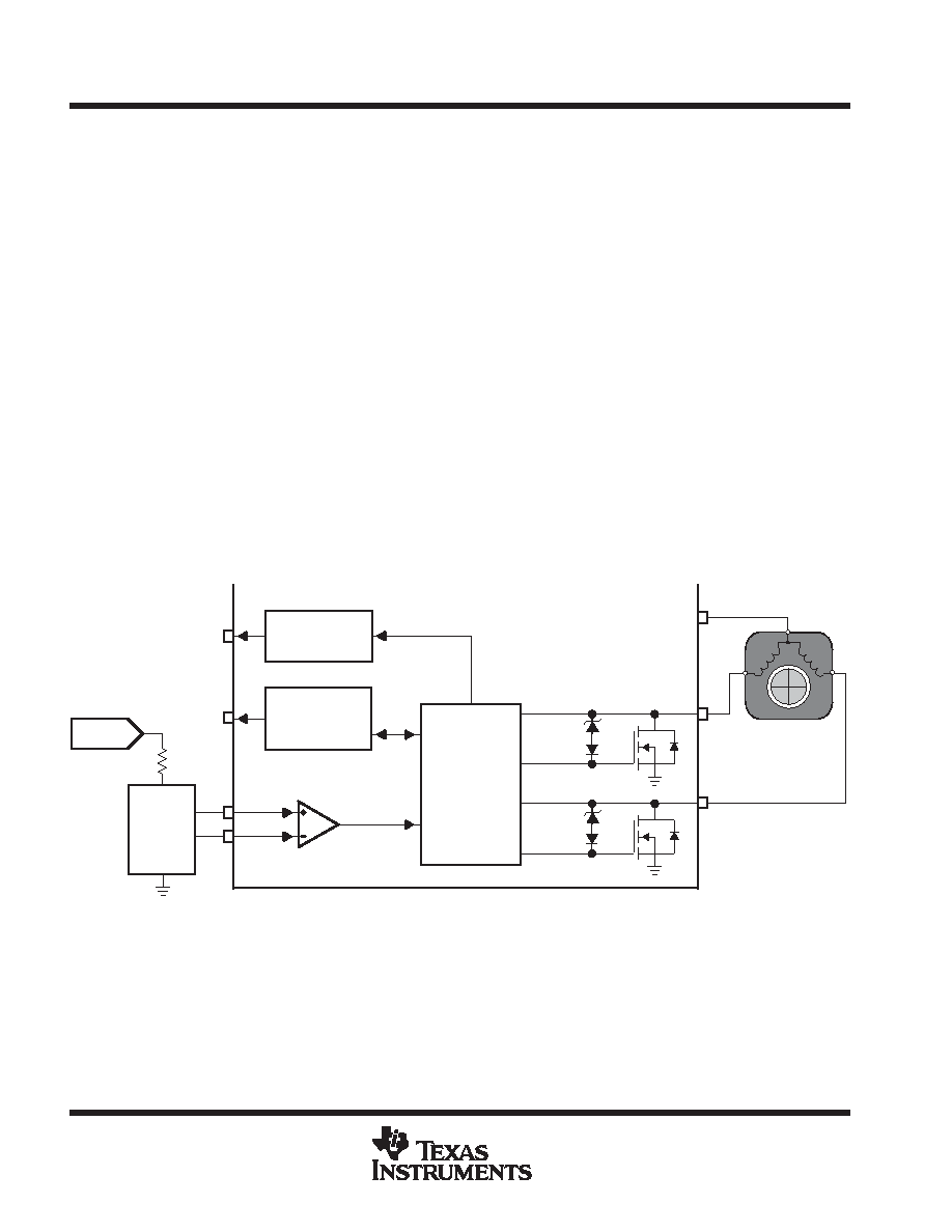
low-side motor phase winding driver outputs (PHA, PHB)
The PHA and PHB outputs provide low-side drive of the motor’s two stator phase windings (see block diagram
and Figure 1). These outputs have a typical RDS(ON) of 400 m at 25°C and a 1-A continuous current rating.
The PHA and PHB outputs have an active flyback clamp (VZCLAMP in Figure 1) of 38 V (typical) to snub inductive
energy when a phase drive switches off. The outputs also have global thermal shutdown to prevent device
failure.
Drive commutation of PHA and PHB outputs is controlled according to rotor position monitored by a Hall-effect
position sensor. Discussion of this function is found in the following section, and the relationship between PHA
and PHB outputs to Hall input signal is shown in Figure 2.
Locked Rotor
Detection and
Auto-Restart
VOUT
TACH
(THMC40)
N
S
N
Tachometer
Output Driver
VZCLAMP
Low-Side
Gate Drive
Control
Logic, and
Global
Thermal
Shutdown
Naked
Hall
Sensor
VPWR
Hall Sensor
Comparator
RD
(THMC41)
H+
H–
PHA
PHB
Figure 1. Low-Side Gate Drive Block Diagram
相关PDF资料 |
PDF描述 |
|---|---|
| THMC40DR | BRUSHLESS DC MOTOR CONTROLLER, 1.5 A, PDSO14 |
| THMC45DGNR | BRUSHLESS DC MOTOR CONTROLLER, PDSO8 |
| THS7002CPWP | SPECIALTY ANALOG CIRCUIT, PDSO28 |
| THS7002IPWP | SPECIALTY ANALOG CIRCUIT, PDSO28 |
| THS7001IPWP | SPECIALTY ANALOG CIRCUIT, PDSO20 |
相关代理商/技术参数 |
参数描述 |
|---|---|
| THMC41SOPD | 制造商:TI 制造商全称:Texas Instruments 功能描述:VARIABLE SPEED 12-VDC BRUSHLESS FAN MOTOR DRIVERS |
| THMC45 | 制造商:TI 制造商全称:Texas Instruments 功能描述:5-V AND 3.3-V DC BRUSHLESS FAN MOTOR DRIVER WITH SINGLE WIRE CONTOL |
| THMC50 | 制造商:TI 制造商全称:Texas Instruments 功能描述:REMOTE/LOCAL TEMPERATURE MONITOR AND FAN CONTROLLER WITH SMBus INTERFACE |
| THMC50DBQR | 制造商:Rochester Electronics LLC 功能描述:- Bulk |
| THMC50SSOPDBQ | 制造商:TI 制造商全称:Texas Instruments 功能描述:REMOTE/LOCAL TEMPERATURE MONITOR AND FAN CONTROLLER WITH SMBus INTERFACE |
发布紧急采购,3分钟左右您将得到回复。