- 您现在的位置:买卖IC网 > PDF目录372454 > TISP61089BD-S (Electronic Theatre Controls, Inc.) TISP61089B High Voltage Ringing SLIC Protector PDF资料下载
参数资料
| 型号: | TISP61089BD-S |
| 厂商: | Electronic Theatre Controls, Inc. |
| 英文描述: | TISP61089B High Voltage Ringing SLIC Protector |
| 中文描述: | TISP61089B高压振铃用户接口保护 |
| 文件页数: | 17/22页 |
| 文件大小: | 411K |
| 代理商: | TISP61089BD-S |
OCTOBER 2000 - REVISED FEBRUARY 2005
Specifications are subject to change without notice.
Customers should verify actual device performance in their specific applications.
TISP61089B High Voltage Ringing SLIC Protector
‘1089 Section 4.5.16 (Continued)
Dedicated intra-building ports may use an R
value of 8
. The 8
value limits the initial current to 13 A, which is within the TISP61089B
single cycle rating. For the TISP61089B to survive the full 900 s test, the series overcurrent protection to operate before the TISP61089B
current-time ratings are exceeded.
Overcurrent and Overvoltage Protection Coordination
To meet ‘1089, the overcurrent protection must be coordinated with the requirements of Sections 4.5.7, 4.5.8, 4.5.9, 4.5.12, 4.5.13, 4.5.15 and
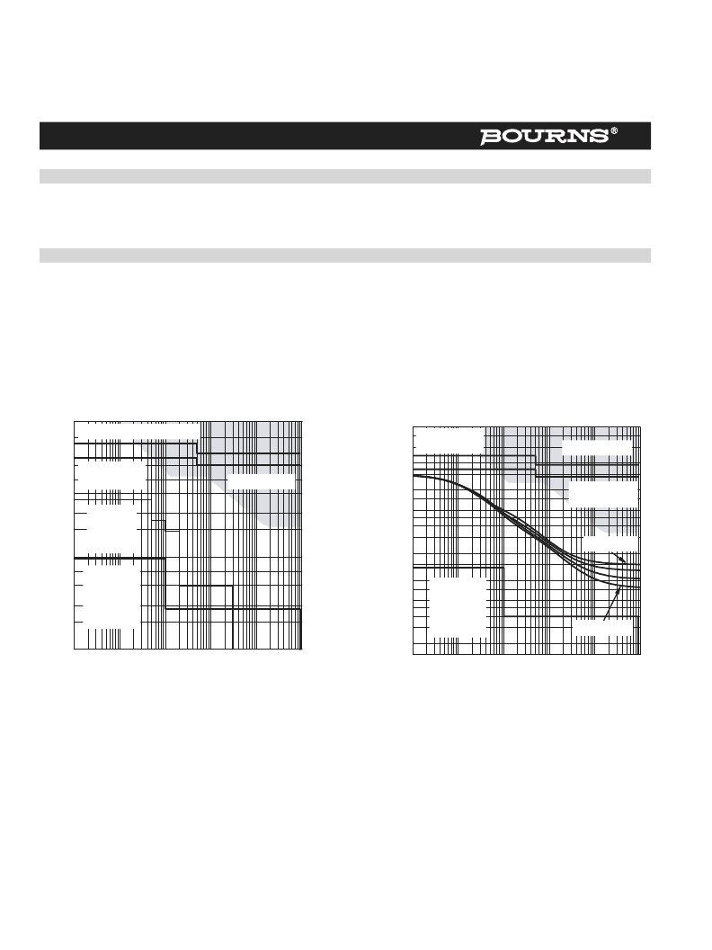
the TISP61089B. The overcurrent protection must not fail in the first-level tests of Sections 4.5.7, 4.5.9 and 4.5.12 (tests 1 through 5). Test 6
through 9 of Section 4.5.12 are not requirements. The test current levels and their duration are shown in Figure 18. First-level tests have a high
source resistance and the current levels are not strongly dependent on the TISP61089B series resistor value.
Second-level tests have a low source resistance and the current levels are dependent on the TISP61089B R
S
resistor value. The two stepped
lines at the top of Figure 18 are for the 25
and 40
series resistor cases. The unacceptable current region (Section 4.5.11) is also shown in
Figure 18. If current flows for the full second-level test time, the unacceptable current region will be entered. The series overcurrent protector
must operate before the unacceptable region is reached.
MAXIMUM RMS CURRENT
vs
TIME
30
Second Level Tests, 25
Figure 18. ‘1089 Test Current Levels
Time - s
0.01
0.1
1
10
100
1000
M
0.1
0.2
0.3
0.5
0.7
1
2
3
5
7
10
20
AI6XAKB
Second Level
Tests, 40
First Level
Tests # 1
through 5,
25
& 40
Objective
First Level
Tests # 6
through 9
Unacceptable
Figure 19.
TISP61089B Overlay
PEAK AC
vs
CURRENT DURATION
t — Current Duration — s
0.01
0.1
1
10
100
1000
P
0.15
0.2
0.3
0.4
0.5
0.8
1.5
2
3
4
5
6
8
15
10
20
30
40
50
1
AI6XDM
Second Level
Tests, 40
Second Level
Tests, 25
Unacceptable
V
GG
= -60 V
First Level
Tests # 1
through 5,
25
& 40
V
GG
= -120 V
Fusible overcurrent protectors cannot operate at first-level current levels. Thus, the permissible low current time-current boundary for fusible
overcurrent protectors is formed by the first-level test currents. Automatically resettable overcurrent protectors (e.g. Positive Temperature
Coefficient Thermistors) may operate during first-level testing, but normal equipment working must be restored after the test has ended.
At system level, the high current boundary is formed by the unacceptable region. However, component and printed wiring, PW, current
limitations will typically lower the high current boundary. Although the series line feed resistance, R
S
, limits the maximum available current in
second-level testing, after about 0.5 s this limitation will exceed the acceptable current flow values.
These three boundaries, first-level, second-level and unacceptable, are replotted in terms of peak current rather than rms current values in
Figure 19. Using a peak current scale allows the TISP61089B longitudinal current rating curves (Figure 3) to be added to Figure 19. Assuming
the PW is sized to adequately carry any currents that may flow, the high current boundary for the overcurrent protector is formed by the
TISP61089B rated current. Note that the TISP61089B rated current curve also depends on the value of gate supply voltage.
相关PDF资料 |
PDF描述 |
|---|---|
| TISP61089BDR-S | TISP61089B High Voltage Ringing SLIC Protector |
| TISP6L7591 | DUAL FORWARD-CONDUCTING P-GATE THYRISTORS PROGRAMMABLE OVERVOLTAGE PROTECTORS |
| TISP6L7591DR-S | DUAL FORWARD-CONDUCTING P-GATE THYRISTORS PROGRAMMABLE OVERVOLTAGE PROTECTORS |
| TISP6L7591DR | DUAL FORWARD-CONDUCTING P-GATE THYRISTORS PROGRAMMABLE OVERVOLTAGE PROTECTORS |
| TL064 | LOW POWER J-FET QUAD OPERATIONAL AMPLIFIERS |
相关代理商/技术参数 |
参数描述 |
|---|---|
| TISP61089BGDR-S | 功能描述:PROTECTOR PROGRAMMABLE SLIC RoHS:是 类别:过电压,电流,温度装置 >> TVS - 晶闸管 系列:- 产品变化通告:Product Discontinuation 19/Jul/2012 标准包装:2,500 系列:- 电压 - 击穿:400V 电压 - 断路:320V 电压 - 导通状态:4V 电流 - 峰值脉冲(8 x 20µs):250A 电流 - 峰值脉冲(10 x 1000µs):80A 电流 - 保持 (Ih):150mA 元件数:1 电容:29pF 封装/外壳:DO-214AA,SMB 包装:带卷 (TR) |
| TISP61089BSDR-S | 功能描述:SCR PROTECTOR - QUAD PROGRAMMABLE RoHS:否 制造商:STMicroelectronics 最大转折电流 IBO:480 A 额定重复关闭状态电压 VDRM:600 V 关闭状态漏泄电流(在 VDRM IDRM 下):5 uA 开启状态 RMS 电流 (It RMS): 正向电压下降:1.6 V 栅触发电压 (Vgt):1.3 V 最大栅极峰值反向电压:5 V 栅触发电流 (Igt):35 mA 保持电流(Ih 最大值):75 mA 安装风格:Through Hole 封装 / 箱体:TO-220 封装:Tube |
| TISP61089D | 功能描述:SCR Dual P Gate Forward Conducting RoHS:否 制造商:STMicroelectronics 最大转折电流 IBO:480 A 额定重复关闭状态电压 VDRM:600 V 关闭状态漏泄电流(在 VDRM IDRM 下):5 uA 开启状态 RMS 电流 (It RMS): 正向电压下降:1.6 V 栅触发电压 (Vgt):1.3 V 最大栅极峰值反向电压:5 V 栅触发电流 (Igt):35 mA 保持电流(Ih 最大值):75 mA 安装风格:Through Hole 封装 / 箱体:TO-220 封装:Tube |
| TISP61089DR | 功能描述:SCR Dual P Gate Forward Conducting RoHS:否 制造商:STMicroelectronics 最大转折电流 IBO:480 A 额定重复关闭状态电压 VDRM:600 V 关闭状态漏泄电流(在 VDRM IDRM 下):5 uA 开启状态 RMS 电流 (It RMS): 正向电压下降:1.6 V 栅触发电压 (Vgt):1.3 V 最大栅极峰值反向电压:5 V 栅触发电流 (Igt):35 mA 保持电流(Ih 最大值):75 mA 安装风格:Through Hole 封装 / 箱体:TO-220 封装:Tube |
| TISP61089DR-S | 功能描述:SCR Dual P Gate Forward Conducting RoHS:否 制造商:STMicroelectronics 最大转折电流 IBO:480 A 额定重复关闭状态电压 VDRM:600 V 关闭状态漏泄电流(在 VDRM IDRM 下):5 uA 开启状态 RMS 电流 (It RMS): 正向电压下降:1.6 V 栅触发电压 (Vgt):1.3 V 最大栅极峰值反向电压:5 V 栅触发电流 (Igt):35 mA 保持电流(Ih 最大值):75 mA 安装风格:Through Hole 封装 / 箱体:TO-220 封装:Tube |
发布紧急采购,3分钟左右您将得到回复。