- 您现在的位置:买卖IC网 > PDF目录299979 > TK7403232LCLEX (TOKO INC) DUAL OUTPUT, FIXED POSITIVE LDO REGULATOR, PDSO8 PDF资料下载
参数资料
| 型号: | TK7403232LCLEX |
| 厂商: | TOKO INC |
| 元件分类: | 固定正电压多路输出LDO稳压器 |
| 英文描述: | DUAL OUTPUT, FIXED POSITIVE LDO REGULATOR, PDSO8 |
| 封装: | SOT-23, 8 PIN |
| 文件页数: | 20/30页 |
| 文件大小: | 913K |
| 代理商: | TK7403232LCLEX |
第1页第2页第3页第4页第5页第6页第7页第8页第9页第10页第11页第12页第13页第14页第15页第16页第17页第18页第19页当前第20页第21页第22页第23页第24页第25页第26页第27页第28页第29页第30页
TOKO@Inc.
IC Data Sheet
TK740xxL
May 2001
GC3-H010 /D
Page 27
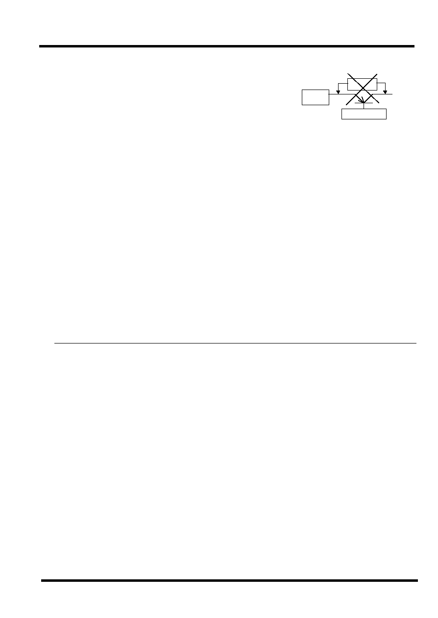
Application @hint
On / off @Control
It is recommended to turn the regulator Off when the circuit following
the regulator is non-operating. A design with a little electric power loss
can be implemented. We recommend the use of the on/off control of the
regulator without using a high side switch to provide an output from
the regulator. A highly accurate output voltage with low voltage drop is
obtained.
Because the control current is small, it is possible to control it directly by CMOS logic.
The PULLDOWN resistance is not built into the control terminal.
The noise and the ripple rejection characteristics depend on the capacitance between the Vout to the Fb
terminal.
The IC will not be damaged if the capacitor value is increased.
Current boost
For current boost applications, use the products below. A low voltage drop, high current regulator can be
easily made.
TK714xx@@
Only the PNP transistor for the current boost is external.
TK732XX@iFor Iout=10A Max regulator)
Built-in Short circuit protection: a constant current can be set by an external resistor.
Definition of Term s
The output voltage tables are specified with a test voltage of Vin = output voltage Typ+1V.
Output Voltage ( Vout)
The output voltage is specified with Vin = output voltage Typ+1V and output current (Iout=5mA).
Maximum Output Current ( Iout Max)
The output current is measured when the output voltage decreases toiVoutTyp.~0.9j. The input voltage is
(output voltage Typ+1V). The maximum output current is measured in a short time so that it is not
influenced by the temperature of the chip.
The output current decreases during low voltage operation.
Please refer to the "Low input voltage-output current" graph for 2.1V or less.
Dropout Voltage ( Vdrop)
The dropout voltage is the difference between the input voltage and the output voltage at which point the
regulator starts to fall out of regulation. Below this value, the output voltage will fall as the input voltage
is reduced. It is dependent upon the load current (Iout) and the junction temperature (Tj).
The input voltage is gradually decreased below the test voltage. It is the voltage difference between the input
and the output when the output voltage decreases by 100mV.
REG
VsatO
P
On/Off Cont.
相关PDF资料 |
PDF描述 |
|---|---|
| TK7403535LCLEX | DUAL OUTPUT, FIXED POSITIVE LDO REGULATOR, PDSO8 |
| TK740SIL-2626 | DUAL OUTPUT, FIXED POSITIVE LDO REGULATOR, PDSO8 |
| TK740SIL-2727 | DUAL OUTPUT, FIXED POSITIVE LDO REGULATOR, PDSO8 |
| TL12W03-L(T30) | SINGLE COLOR LED, WARM WHITE |
| TL6700AF160QJ | KEYPAD SWITCH, SPST, MOMENTARY, 0.05A, 12VDC, 2.06 N, SURFACE MOUNT-STRAIGHT |
相关代理商/技术参数 |
参数描述 |
|---|---|
| TK7408 | 制造商:Tekmos 功能描述:IC, PLCC-44 |
| TK75 | 制造商:ALTECH 制造商全称:Altech corporation 功能描述:POLYCARBONATE ENCLOSURE TK 75 |
| TK7500 | 功能描述:冲压机与冲模 FRM W/4 DIES & CASE RoHS:否 制造商:Souriau 大小: 产品:Dies 类型:Crimping 描述/功能: |
| TK75001 | 制造商:TOKO 制造商全称:TOKO, Inc 功能描述:PWM CONTROLLER |
| TK75001D | 制造商:TOKO 制造商全称:TOKO, Inc 功能描述:PWM CONTROLLER |
发布紧急采购,3分钟左右您将得到回复。