- 您现在的位置:买卖IC网 > PDF目录98238 > TLC2574IPWR (TEXAS INSTRUMENTS INC) 4-CH 12-BIT SUCCESSIVE APPROXIMATION ADC, SERIAL ACCESS, PDSO20 PDF资料下载
参数资料
| 型号: | TLC2574IPWR |
| 厂商: | TEXAS INSTRUMENTS INC |
| 元件分类: | ADC |
| 英文描述: | 4-CH 12-BIT SUCCESSIVE APPROXIMATION ADC, SERIAL ACCESS, PDSO20 |
| 封装: | GREEN, PLASTIC, TSSOP-20 |
| 文件页数: | 11/48页 |
| 文件大小: | 1092K |
| 代理商: | TLC2574IPWR |
第1页第2页第3页第4页第5页第6页第7页第8页第9页第10页当前第11页第12页第13页第14页第15页第16页第17页第18页第19页第20页第21页第22页第23页第24页第25页第26页第27页第28页第29页第30页第31页第32页第33页第34页第35页第36页第37页第38页第39页第40页第41页第42页第43页第44页第45页第46页第47页第48页
TLC3574, TLC3578, TLC2574, TLC2578
5V ANALOG, 3/5V DIGITAL, 14/12BIT, 200KSPS, 4/8CHANNEL
SERIAL ANALOGTODIGITAL CONVERTERS WITH ±10V INPUTS
SLAS262C OCTOBER 2000 REVISED MAY 2003
19
WWW.TI.COM
circuit description (continued)
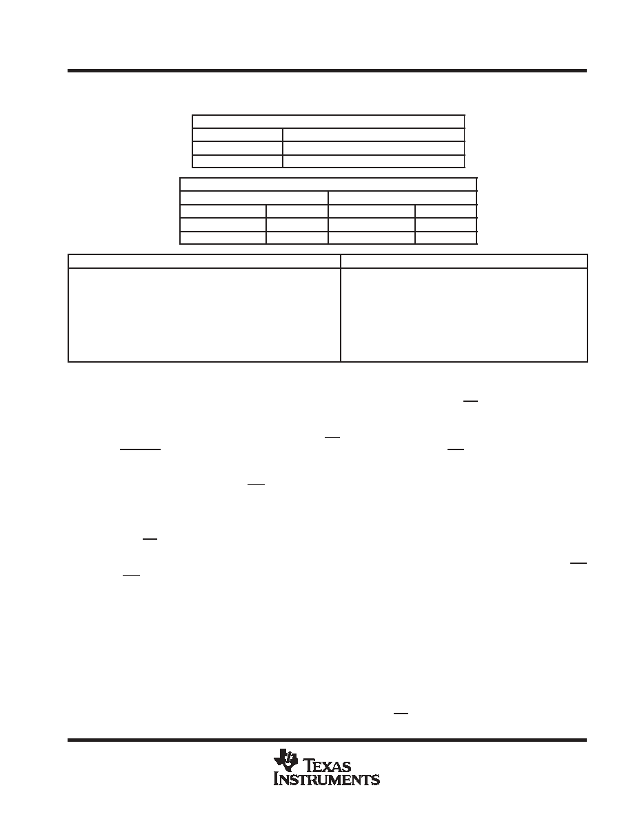
data format
INPUT DATA FORMAT (BINARY)
MSB
LSB
ID[15:12]
ID[11:0]
Command
Configuration data field or filled with zeros
OUTPUT DATA FORMAT (READ CONVERSION/FIFO)
TLC3574 and TLC3578
TLC2574 and TLC2578
MSB
LSB
MSB
LSB
OD[15:2]
OD[1:0]
OD[15:4]
OD[3:0]
Conversion result
Don’t Care
Conversion result
Don’t Care
14-BIT (TLC3574/78)
12-BIT (TLC2574/78)
Bipolar Input, Offset Binary: (BOB)
Negative full scale code = VFS = 0000h, Vcode = 10 V
Midscale code = VBZS = 2000h, Vcode = 0 V
Positive full scale code = VFS+ = 3FFFh, Vcode = 10 V 1 LSB
Bipolar Input, Binary 2s Complement: (BTC)
Negative full scale code = VFS = 2000 h, Vcode = 10 V
Midscale code = VBZS = 0000h, Vcode = 0 V
Positive full scale code = VFS+ = 1FFFh, Vocde = 10 V 1 LSB
Bipolar Offset Binary Output: (BOB)
Negative full scale code = 000h, Vcode = 10 V
Midscale code = 800h, Vcode = 0 V
Positive full scale code = FFFh, Vcode = 10 V 1 LSB
Bipolar Input, Binary 2s Complement: (BTC)
Negative full scale code = 800 h, Vcode = 10 V
Midscale code = 000h, Vcode = 0 V
Positive full scale code = 7FFh, Vocde = 10 V 1 LSB
operation description
The converter samples the selected analog input signal, then converts the sample into digital output according
to the selected output format. The converter has four digital input pins (SDI, SCLK, CS, and FS) and one digital
output pin (SDO) to communicate with the host device. SDI is a serial data input pin, SDO is a serial data output
pin, and SCLK is a serial clock from host device. This clock is used to clock the serial data transfer. It can also
be used as conversion clock source (see Table 2). CS and FS are used to start the operation. The converter
has a CSTART pin for external hardware sampling and conversion trigger, and INT/EOC for interrupt purpose.
device initialization
After power on, the status of EOC/INT is initially high, and the input data register is set to all zeros. The device
must be initialized before starting conversion. The initialization procedure depends on the working mode. The
first conversion result must be ignored after power on.
Hardware Default Mode: Nonprogrammed mode, default. After power on, two consecutive active cycles
initiated by CS or FS put the device into hardware default mode if SDI is tied to DVDD. Each of these cycles must
last 16 SCLK at least. These cycles initialize the converter and load CFR register with 800h (bipolar offset binary
output code, normal long sampling, internal OSC, single-ended input, one-shot conversion mode, and EOC/INT
pin as INT). No additional software configuration is required.
Software Programmed Mode: Programmed. If the converter needs to be configured, The host must write
A000H into converters first after power on, then performs the WRITE CFR operation to configure the device.
start of operation cycle
Each operation consists of several actions that the converter takes according to the command from the host.
The operation cycle includes three periods: command period, sampling period, and conversion period. In the
command period, the device decodes the command from host. In the sampling period, the device samples the
selected analog signal according to the command. In the conversion period, the sample of the analog signal
is converted to digital format. The operation cycle starts from the command period, which is followed by one
or several sampling and conversion periods (depending on the setting), and finishes at the end of last
conversion period. The operation is initiated by the falling edge of CS or the rising edge of FS.
相关PDF资料 |
PDF描述 |
|---|---|
| TLC2574IDWR | 4-CH 12-BIT SUCCESSIVE APPROXIMATION ADC, SERIAL ACCESS, PDSO20 |
| TLC32070N | SPECIALTY ANALOG CIRCUIT, PDIP28 |
| TLC32070FN | SPECIALTY ANALOG CIRCUIT, PQCC28 |
| TLC32071FN | PARALLEL, 8 BITS INPUT LOADING, 8 us SETTLING TIME, 8-BIT DAC, PQCC28 |
| TLC32071N | PARALLEL, 8 BITS INPUT LOADING, 8 us SETTLING TIME, 8-BIT DAC, PDIP28 |
相关代理商/技术参数 |
参数描述 |
|---|---|
| TLC2574IPWRG4 | 功能描述:模数转换器 - ADC Serial Out Low Power RoHS:否 制造商:Texas Instruments 通道数量:2 结构:Sigma-Delta 转换速率:125 SPs to 8 KSPs 分辨率:24 bit 输入类型:Differential 信噪比:107 dB 接口类型:SPI 工作电源电压:1.7 V to 3.6 V, 2.7 V to 5.25 V 最大工作温度:+ 85 C 安装风格:SMD/SMT 封装 / 箱体:VQFN-32 |
| TLC2578EVM | 功能描述:数据转换 IC 开发工具 TLC2578 Eval Mod RoHS:否 制造商:Texas Instruments 产品:Demonstration Kits 类型:ADC 工具用于评估:ADS130E08 接口类型:SPI 工作电源电压:- 6 V to + 6 V |
| TLC2578IDW | 功能描述:模数转换器 - ADC Serial Out Low Power RoHS:否 制造商:Texas Instruments 通道数量:2 结构:Sigma-Delta 转换速率:125 SPs to 8 KSPs 分辨率:24 bit 输入类型:Differential 信噪比:107 dB 接口类型:SPI 工作电源电压:1.7 V to 3.6 V, 2.7 V to 5.25 V 最大工作温度:+ 85 C 安装风格:SMD/SMT 封装 / 箱体:VQFN-32 |
| TLC2578IDWG4 | 功能描述:模数转换器 - ADC Serial Out Low Power RoHS:否 制造商:Texas Instruments 通道数量:2 结构:Sigma-Delta 转换速率:125 SPs to 8 KSPs 分辨率:24 bit 输入类型:Differential 信噪比:107 dB 接口类型:SPI 工作电源电压:1.7 V to 3.6 V, 2.7 V to 5.25 V 最大工作温度:+ 85 C 安装风格:SMD/SMT 封装 / 箱体:VQFN-32 |
| TLC2578IDWR | 功能描述:模数转换器 - ADC Serial Out Low Power RoHS:否 制造商:Texas Instruments 通道数量:2 结构:Sigma-Delta 转换速率:125 SPs to 8 KSPs 分辨率:24 bit 输入类型:Differential 信噪比:107 dB 接口类型:SPI 工作电源电压:1.7 V to 3.6 V, 2.7 V to 5.25 V 最大工作温度:+ 85 C 安装风格:SMD/SMT 封装 / 箱体:VQFN-32 |
发布紧急采购,3分钟左右您将得到回复。