- 您现在的位置:买卖IC网 > PDF目录220057 > TPB-5/5-15/1-Q12 (CD TECHNOLOGIES INC) 3-OUTPUT 25 W DC-DC REG PWR SUPPLY MODULE PDF资料下载
参数资料
| 型号: | TPB-5/5-15/1-Q12 |
| 厂商: | CD TECHNOLOGIES INC |
| 元件分类: | 电源模块 |
| 英文描述: | 3-OUTPUT 25 W DC-DC REG PWR SUPPLY MODULE |
| 文件页数: | 2/6页 |
| 文件大小: | 122K |
| 代理商: | TPB-5/5-15/1-Q12 |
25-40W , TRIPLE
OUTPUT
DC/DC
CONVER TERS
XPB Series
2
Typical at TA = +25°C under nominal line voltage and "full-load" conditions unless otherwise
noted. The specific combination of primary and auxiliary currents comprising "full load" varies
with part number. See Ouput Power Considerations and Technical Notes for more details.
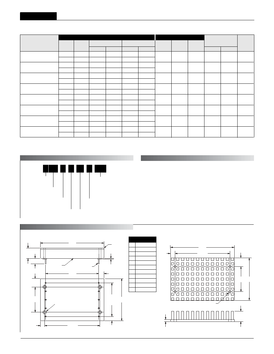
I/O Connections
Function P16
No Pin
–Input
+Input
Case
On/Off Control*
–12V/15V Out
+12V/15V Out
Common
+5V Out
Trim
Pin
1
2
3
4
5
6
7
8
9
10
* See note 4 on next page.
Input Voltage Range:
Q12 = 10-36 Volts (24V nom.)
D24 = 18-36 Volts (24V nom.)
Q48 = 18-72 Volts (48V nom.)
D48 = 36-72 Volts (48V nom.)
Nominal Auxiliary Output
Voltages (±12 or ±15 Volts)
Output Configuration:
T = Triple
Nominal Primary Output
Voltage (+5 Volts)
5
T PB
5
-/
D48
-
Maximum Primary Output
Current in Amps
Power Package with
Metal Baseplate
12 1
-
/
Maximum Auxiliary Output
Currents in Amps from each output
TPB-5/5-12/1-Q12
TPB-5/5-12/1-D24
TPB-5/5-12/1-Q48
TPB-5/5-12/1-D48
TPB-5/5-15/1-Q12
TPB-5/5-15/1-D24
TPB-5/5-15/1-Q48
TPB-5/5-15/1-D48
+5
±12
+5
±12
+5
±12
+5
±12
+5
±15
+5
±15
+5
±15
+5
±15
Performance Specifications and Ordering Guide
IOUT
(Amps)
R/N (mVp-p)
Load
VOUT
(Volts)
Output
Package
(Case,
Pinout)
Efficiency
Regulation (Max.)
Line
VIN Nom.
(Volts)
Range
(Volts)
Model
Input
IIN
(mA)
Max.
Typ.
Min.
10-36
18-36
18-72
36-72
10-36
18-36
18-72
36-72
24
48
24
48
C10, P16
5
±1
5
±1
5
±1
5
±1
5
±1
5
±1
5
±1
5
±1
125
120
125
120
125
120
125
120
125
150
125
150
125
150
125
150
±1%
±1.5%
±1%
±1.5%
±1%
±1.5%
±1%
±1.5%
±1%
±1.5%
±1%
±1.5%
±1%
±1.5%
±1%
±1.5%
±8%
±1.5%
±8%
±1.5%
±8%
±1.5%
±8%
±1.5%
±8%
±1.5%
±8%
±1.5%
±8%
±1.5%
±8%
35/1240
35/1716
20/737
25/967
35/1238
35/1696
20/735
25/981
82%
83%
82%
83%
82%
83%
82%
83%
PAR T NUMBER STR UCTURE
Model
Maximum Output Power
Q12
25 Watts
Q48
30 Watts
D24
35 Watts
D48
40 Watts
MECHANICAL SPECIFICA TIONS
As shown below, TPB Model DC/DC Converters are classified by output power.
For triple-output devices, the sum of the output power from the primary +5V
output plus that from the two auxiliary (±12V or ±15V) outputs can not exceed
the rated power. For example, "D24" models have a maximum power of 35W.
Therefore, if you source the maximum primary current of 5A, the devices will
only be able to provide 10W of total power from their auxilliary outputs.
75
100
75
100
75
100
75
100
75
120
75
120
75
120
75
120
84%
85%
86%
85%
86%
85%
Ripple/Noise (R/N) measured over a 20MHz bandwidth.
10-100% load on the primary +5V output, 20-100% balanced loads on the auxiliary outputs.
Nominal line voltage, no-load/full-load conditions.
OUTPUT PO WER CONSIDERA TIONS
2.600
(66.04)
0.20
(5.08)
2.00
(50.80)
1.200
(30.48)
3.00
(76.20)
0.50
(12.70)
0.40
(10.16)
0.10
(2.54)
0.120 DIA. (3.048)
(4 PLACES)
MATERIAL: BLACK ANODIZED ALUMINUM
4 MOUNTING SCREWS AND 0.009 (0.229) THERMAL PAD INCLUDED
TOP VIEW
Optional Heat Sink (Part Number HS-23)
BOTTOM VIEW
2.500
(63.50)
0.25
(6.35)
2.00
(50.80)
7
6
8
9
1.600
(40.64)
4 EQ. SP. @
0.400 (10.16)
4
1
2
0.20
(5.08)
1.200
(30.48)
2.600
(66.04)
0.40
(10.16)
3.00
(76.20)
(4) THREADED INSERTS
#4-40 THD THRU
WITH 0.025 (0.64)
STANDOFFS
0.20
(5.08)
3
5
10
0.50
(12.70)
0.20 MIN.
(5.08)
0.040 ±0.002 DIA.
(1.016 ±0.051)
0.025
(0.64)
METAL CASE
METAL
BASEPLATE
Case C10
相关PDF资料 |
PDF描述 |
|---|---|
| TL4051CQDBZRG4 | 1-OUTPUT TWO TERM VOLTAGE REFERENCE, 1.212 V, PDSO3 |
| TPS61202DSCR | 1.5 A BATTERY CHARGE CONTROLLER, 1650 kHz SWITCHING FREQ-MAX, PDSO10 |
| TC1121EOA723 | SWITCHED CAPACITOR CONVERTER, 200 kHz SWITCHING FREQ-MAX, PDSO8 |
| TD300-150-28-MP | 1-OUTPUT 300 W DC-DC REG PWR SUPPLY MODULE |
| TPS3824-30QDBVRQ1 | 1-CHANNEL POWER SUPPLY MANAGEMENT CKT, PDSO5 |
相关代理商/技术参数 |
参数描述 |
|---|---|
| TPB6 | 功能描述:电气外壳 N4X ENCLOSURE NON METALLIC RoHS:否 制造商:Bud Industries 产品:Wall Mount Enclosures 类型:Single Door NEMA 额定值:3R 外部深度:254 mm 外部高度:305 mm 外部宽度:305 mm 面板宽度:261 mm 面板高度:261 mm 材料:Steel 颜色:Gray 通风:Not Available |
| TPB62 | 功能描述:硅对称二端开关元件 RO 511-SMP100LC-65 CB429 62V 100A TRIS RoHS:否 制造商:Bourns 转折电流 VBO:40 V 最大转折电流 IBO:800 mA 不重复通态电流: 额定重复关闭状态电压 VDRM:25 V 关闭状态漏泄电流(在 VDRM IDRM 下): 保持电流(Ih 最大值):50 mA 开启状态电压:5 V 关闭状态电容 CO:120 pF 最大工作温度:+ 150 C 安装风格:SMD/SMT 封装 / 箱体:DO-214AA |
| TP-B6267-1 | 功能描述:按钮开关 TP-B6267-1 RoHS:否 制造商:C&K Components 触点形式:2 NC - 2 NO 开关功能:ON ? OFF 电流额定值:4 A 电压额定值 AC:12 V to 250 V 电压额定值 DC:12 V to 50 V 功率额定值: 安装风格:Through Hole 照明:Illuminated 照明颜色:None IP 等级:IP 40 端接类型:Solder 触点电镀:Silver 执行器:Square 盖颜色: 封装: 可燃性等级:UL 94 V-0 |
| TP-B6267-5 | 制造商:TE Connectivity 功能描述:D60904-000 |
| TPB62A18 | 制造商:STMicroelectronics 功能描述:Transient Suppressor Diode, Single, Bi-Directional, 56 Volt, Axial-9 |
发布紧急采购,3分钟左右您将得到回复。