- 您现在的位置:买卖IC网 > PDF目录98278 > TPS2000CDGN (TEXAS INSTRUMENTS INC) SPECIALTY ANALOG CIRCUIT, PDSO8 PDF资料下载
参数资料
| 型号: | TPS2000CDGN |
| 厂商: | TEXAS INSTRUMENTS INC |
| 元件分类: | 模拟信号调理 |
| 英文描述: | SPECIALTY ANALOG CIRCUIT, PDSO8 |
| 封装: | PLASTIC, MSOP-8 |
| 文件页数: | 6/28页 |
| 文件大小: | 1476K |
| 代理商: | TPS2000CDGN |
第1页第2页第3页第4页第5页当前第6页第7页第8页第9页第10页第11页第12页第13页第14页第15页第16页第17页第18页第19页第20页第21页第22页第23页第24页第25页第26页第27页第28页
V
O
U
T
IOUT
IOS
Decreasing
Load
Resistance
VIN
0 A
0 V
Slope = -RDS(ON)
V
O
U
T
IOUT
IOS
Decreasing
Load
Resistance
VIN
0 A
0 V
Slope = -RDS(ON)
IOC
Current Limit
with Peaking
Flat Current
Limit
SLVSAU6B
– JUNE 2011 – REVISED SEPTEMBER 2011
The TPS20xxC thermal cycles if an overload condition is present long enough to activate thermal limiting in any
of the above cases. This is due to the relatively large power dissipation [(VIN – VOUT) x IOS] driving the junction
temperature up. The device turns off when the junction temperature exceeds 135
°C (min) while in current limit.
The device remains off until the junction temperature cools 20
°C and then restarts.
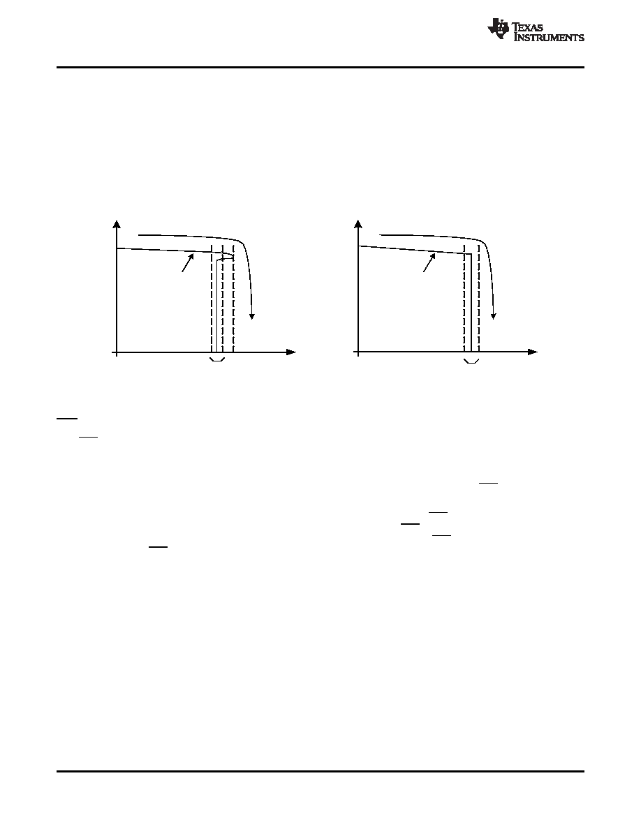
There are two kinds of current limit profiles typically available in TI switch products similar to the TPS20xxC.
Many older designs have an output I vs V characteristic similar to the plot labeled "Current Limit with Peaking" in
Figure 40. This type of limiting can be characterized by two parameters, the current limit corner (IOC), and the
short circuit current (IOS). IOC is often specified as a maximum value. The TPS20xxC family of parts does not
present noticeable peaking in the current limit, corresponding to the characteristic labeled "Flat Current Limit" in
Figure 40. Current Limit Profiles
FLT
The FLT open-drain output is asserted (active low) during an overload or over-temperature condition. A 9 ms
deglitch on both the rising and falling edges avoids false reporting at startup and during transients. A current limit
condition shorter than the deglitch period will clear the internal timer upon termination. The deglitch timer will not
integrate multiple short overloads and declare a fault. This is also true for exiting from a faulted state. An input
voltage with excessive ripple and large output capacitance may interfere with operation of FLT around IOS as the
ripple will drive the TPS20xxC in and out of current limit.
If the TPS20xxC is in current limit and the over-temperature circuit goes active, FLT will go true immediately (see
Figure 12) however exiting this condition is deglitched (see Figure 14). FLT is tripped just as the knee of the
constant-current limiting is entered. Disabling the TPS20xxC will clear an active FLT as soon as the switch turns
off (see Figure 11). FLT is high impedance when the TPS20xxC is disabled or in under-voltage lockout (UVLO).
OUTPUT DISCHARGE
A 470
(typical) output discharge will dissipate stored charge and leakage current on OUT when the TPS20xxC
is in UVLO or disabled. The pull-down circuit will lose bias gradually as VIN decreases, causing a rise in the
discharge resistance as VIN falls towards 0 V.
14
Copyright
2011, Texas Instruments Incorporated
Product Folder Link(s) :TPS20xxC
相关PDF资料 |
PDF描述 |
|---|---|
| TPS2010APWPR | 1-CHANNEL POWER SUPPLY SUPPORT CKT, PDSO14 |
| TPS2012APWPG4 | 1-CHANNEL POWER SUPPLY SUPPORT CKT, PDSO14 |
| TPS2010APWPRG4 | 1-CHANNEL POWER SUPPLY SUPPORT CKT, PDSO14 |
| TPS2012PWR | 1-CHANNEL POWER SUPPLY SUPPORT CKT, PDSO14 |
| TPS2013PWR | 1-CHANNEL POWER SUPPLY SUPPORT CKT, PDSO14 |
相关代理商/技术参数 |
参数描述 |
|---|---|
| TPS2000CDGNR | 功能描述:电源开关 IC - USB SGL CH,CURRENT-LTD USB PWR DISTR SWITCH RoHS:否 制造商:Micrel 电源电压-最小:2.7 V 电源电压-最大:5.5 V 最大工作温度:+ 85 C 最小工作温度:- 40 C 封装 / 箱体:SOIC-8 封装:Tube |
| TPS2001C-2 | 制造商:TI 制造商全称:Texas Instruments 功能描述:Current-Limited, Power-Distribution Switches |
| TPS2001CDGK | 功能描述:电源开关 IC - USB Sgl Channel,Crnt-Ltd USB Pwr Dist Switch RoHS:否 制造商:Micrel 电源电压-最小:2.7 V 电源电压-最大:5.5 V 最大工作温度:+ 85 C 最小工作温度:- 40 C 封装 / 箱体:SOIC-8 封装:Tube |
| TPS2001CDGKR | 功能描述:电源开关 IC - USB Sgl Channel,Crnt-Ltd USB Pwr Dist Switch RoHS:否 制造商:Micrel 电源电压-最小:2.7 V 电源电压-最大:5.5 V 最大工作温度:+ 85 C 最小工作温度:- 40 C 封装 / 箱体:SOIC-8 封装:Tube |
| TPS2001CDGN | 功能描述:电源开关 IC - USB SGL CH,CURRENT-LTD USB PWR DISTR SWITCH RoHS:否 制造商:Micrel 电源电压-最小:2.7 V 电源电压-最大:5.5 V 最大工作温度:+ 85 C 最小工作温度:- 40 C 封装 / 箱体:SOIC-8 封装:Tube |
发布紧急采购,3分钟左右您将得到回复。