- 您现在的位置:买卖IC网 > PDF目录69509 > TPS40192DRCRG4 (TEXAS INSTRUMENTS INC) SWITCHING CONTROLLER, 700 kHz SWITCHING FREQ-MAX, PDSO10 PDF资料下载
参数资料
| 型号: | TPS40192DRCRG4 |
| 厂商: | TEXAS INSTRUMENTS INC |
| 元件分类: | 稳压器 |
| 英文描述: | SWITCHING CONTROLLER, 700 kHz SWITCHING FREQ-MAX, PDSO10 |
| 封装: | 3 X 3 MM, GREEN, PLASTIC, SON-10 |
| 文件页数: | 18/38页 |
| 文件大小: | 707K |
| 代理商: | TPS40192DRCRG4 |
第1页第2页第3页第4页第5页第6页第7页第8页第9页第10页第11页第12页第13页第14页第15页第16页第17页当前第18页第19页第20页第21页第22页第23页第24页第25页第26页第27页第28页第29页第30页第31页第32页第33页第34页第35页第36页第37页第38页
R7 +
V
FB
R8
V
OUT * VFB
A
PS(fco) + AMOD(dc) * 40
LOG
f
CO
f
RES
C2 +
1
2p
R8
f
Z2
R10 +
1
2p
C2
f
P1
R6 +
A
MID(band)
(R10
R8)
R10 ) R8
www.ti.com
SLUS719C – MARCH 2007 – REVISED AUGUST 2010
(30)
VFB = 0.591 V and R8 = 20 k for VOUT = 1.8 V, R7 = 9.78 k, so the value of 9.76 k is selected as the closest
standard value. A slightly lower nominal value increases the nominal output voltage slightly to compensate for
some trace impedance at load.
Error Amplifier Compensation (R6, R10, C1, C2, C3)
Place two zeros at 50% and 100% of the resonance frequency to boost the phase margin before resonance
frequency generates -180° of phase shift. For fRES = 11.7 kHz, FZ1 = 5.8 kHz and FZ2 = 11 kHz. Selecting the
crossover frequency (fCO) of the control loop between 3 times the LC filter resonance and 1/5th the switching
frequency. For most applications 1/10th the switching frequency provides a good balance between ease of
design and fast transient response.
If fESR < fCO FP1 = fESR and FP2 = 4 × fCO.
If fESR > 2 × fCO; FP1 = fCO and FP2 = 8 × fCO.
For this design
fSW = 600 kHz,
fRES = 11.7 kHz
fESR = 636 kHz
fCO = 60 kHz and since
fESR > 2 × fCO, FP1 = fCO = 60 kHz and FP2 = 4 × fCO = 500 kHz.
(31)
APS(FCC) = -5.4 dB, and the error amplifier gain between the poles should be should be 10
5.4 dB/20 = 1.86.
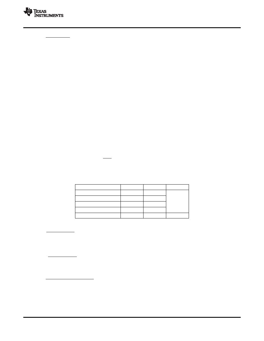
Table 6. Error Amplifier Design Parameters
PARAMETER
SYMBOL
VALUE
UNITS
First zero frequency
FZ1
5.8
Second zero frequency
FZ2
11.0
kHz
First pole frequency
FP1
60
Second pole frequency
FP2
500
Midband gain
AMID(band)
1.86
V/V
Approximate C2 with the formula described in Equation 32.
(32)
C2 = 1000 pf (A standard capacitor value to calculated 723 pF) and approximate R6 with the formula described
in Equation 33.
(33)
R10 = 2.61 k
(Closest standard resistor value to calculated 2.65 k ) Calculate R3 with Equation 34.
(34)
With AMID(band) = 1.86, R10 = 2.61 k and R8 = 20 k , R6 = 4.22 k (Closest standard resistor value to
calculated 4.29 k
).
Calculate C1 and C3 using Equation 35 and Equation 36.
Copyright 2007–2010, Texas Instruments Incorporated
25
相关PDF资料 |
PDF描述 |
|---|---|
| TPS40192DRCTG4 | SWITCHING CONTROLLER, 700 kHz SWITCHING FREQ-MAX, PDSO10 |
| TPS40193DRCR | SWITCHING CONTROLLER, 360 kHz SWITCHING FREQ-MAX, PDSO10 |
| TPS40195RGYR | SWITCHING CONTROLLER, 580 kHz SWITCHING FREQ-MAX, PQCC16 |
| TPS40195PWG4 | SWITCHING CONTROLLER, 580 kHz SWITCHING FREQ-MAX, PDSO16 |
| TPS40195PW | SWITCHING CONTROLLER, 580 kHz SWITCHING FREQ-MAX, PDSO16 |
相关代理商/技术参数 |
参数描述 |
|---|---|
| TPS40192DRCT | 功能描述:DC/DC 开关控制器 4.5V-8V Input Synch Buck Contr RoHS:否 制造商:Texas Instruments 输入电压:6 V to 100 V 开关频率: 输出电压:1.215 V to 80 V 输出电流:3.5 A 输出端数量:1 最大工作温度:+ 125 C 安装风格: 封装 / 箱体:CPAK |
| TPS40192DRCTG4 | 功能描述:DC/DC 开关控制器 4.5V-18V Input Synch Buck Cntrlr RoHS:否 制造商:Texas Instruments 输入电压:6 V to 100 V 开关频率: 输出电压:1.215 V to 80 V 输出电流:3.5 A 输出端数量:1 最大工作温度:+ 125 C 安装风格: 封装 / 箱体:CPAK |
| TPS40192EVM-001 | 功能描述:电源管理IC开发工具 TPS40192 Evaluation Module RoHS:否 制造商:Maxim Integrated 产品:Evaluation Kits 类型:Battery Management 工具用于评估:MAX17710GB 输入电压: 输出电压:1.8 V |
| TPS40192EVM-525 | 功能描述:电源管理IC开发工具 TPS40192EVM-525 Eval mod RoHS:否 制造商:Maxim Integrated 产品:Evaluation Kits 类型:Battery Management 工具用于评估:MAX17710GB 输入电压: 输出电压:1.8 V |
| TPS40193 | 制造商:TI 制造商全称:Texas Instruments 功能描述:4.5-V TO 18-V INPUT 10-PIN SYNCHRONOUS BUCK CONTROLLER WITH POWER GOOD |
发布紧急采购,3分钟左右您将得到回复。