- 您现在的位置:买卖IC网 > PDF目录69509 > TPS40210QDGQRQ1 (TEXAS INSTRUMENTS INC) SWITCHING REGULATOR, 1000 kHz SWITCHING FREQ-MAX, PDSO10 PDF资料下载
参数资料
| 型号: | TPS40210QDGQRQ1 |
| 厂商: | TEXAS INSTRUMENTS INC |
| 元件分类: | 稳压器 |
| 英文描述: | SWITCHING REGULATOR, 1000 kHz SWITCHING FREQ-MAX, PDSO10 |
| 封装: | GREEN, PLATSIC, MSOP-10 |
| 文件页数: | 5/41页 |
| 文件大小: | 999K |
| 代理商: | TPS40210QDGQRQ1 |
第1页第2页第3页第4页当前第5页第6页第7页第8页第9页第10页第11页第12页第13页第14页第15页第16页第17页第18页第19页第20页第21页第22页第23页第24页第25页第26页第27页第28页第29页第30页第31页第32页第33页第34页第35页第36页第37页第38页第39页第40页第41页
T
8
10
2
7
4
6
9
2
SW
T
SW
T
1
R
5.8
10
f
C
8
10
f
1.4
10
f
1.5
10
1.7
10
C
4
10
C
-
=
+
+
-
+
-
+
1
RC
150 mV
S
Q
R
+
8
5
VDD
GND
R
RC
C
RC
CLK
External Frequency
Synchronization
(optional)
V
IN
TPS40210/11
UDG-08063
www.ti.com
SLVS861D – AUGUST 2008 – REVISED APRIL 2010
Setting the Oscillator Frequency
The oscillator frequency is determined by a resistor and capacitor connected to the RC pin of the TPS40210. The
capacitor is charged to a level of approximately VVDD/20 by current flowing through the resistor and is then
discharged by a transistor internal to the TPS40210. The required resistor for a given oscillator frequency is
found from either Figure 1 or Equation 5.
where
RT is the timing resistance in k
f SW is the switching frequency in kHz
CT is the timing capacitance in pF
(5)
For most applications, a capacitor in the range of 68 pF to 120 pF gives the best results. Resistor values should
be limited to between 100 k
and 1 M as well. If the resistor value falls below 100 k, decrease the capacitor
size and recalculate the resistor value for the desired frequency. As the capacitor size decreases below 47 pF,
the accuracy of Equation 5 degrades, and empirical means may be needed to fine tune the timing component
values to achieve the desired switching frequency.
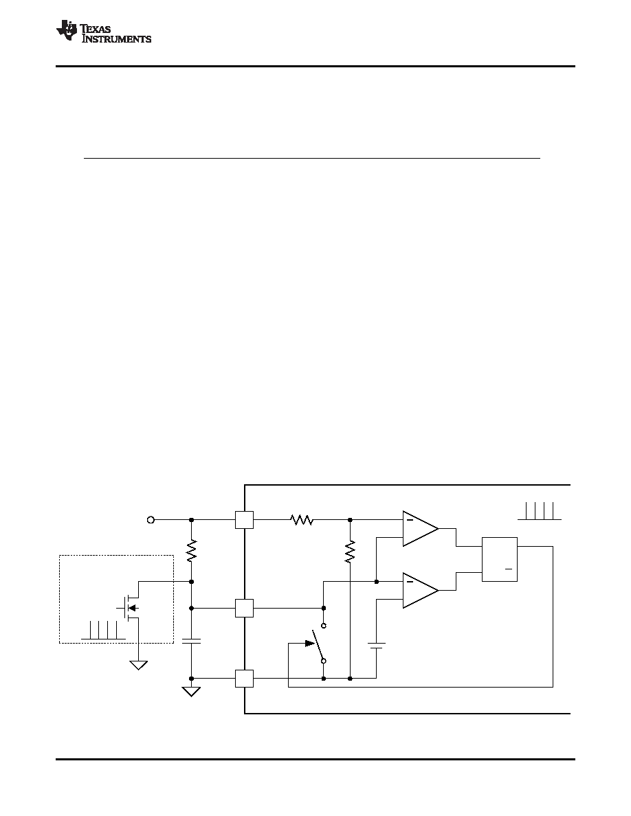
Synchronizing the Oscillator
The TPS40210 and TPS40211 can be synchronized to an external clock source. Figure 20 shows the functional
diagram of the oscillator. When synchronizing the oscillator to an external clock, the RC pin must be pulled below
150 mV for 20 ns or more. The external clock frequency must be higher than the free running frequency of the
converter as well. When synchronizing the controller, if the RC pin is held low for an excessive amount of time,
erratic operation may occur. The maximum amount of time that the RC pin should be held low is 50% of a
nominal output pulse, or 10% of the period of the synchronization frequency.
Under circumstances where the duty cycle is less than 50%, a Schottky diode connected from the RC pin to an
external clock may be used to synchronize the oscillator. The cathode of the diode is connected to the RC pin.
The trip point of the oscillator is set by an internal voltage divider to be 1/20 of the input voltage. The clock signal
must have an amplitude higher than this trip point. When the clock goes low, it allows the reset current to restart
the RC ramp, synchronizing the oscillator to the external clock. This provides a simple single-component method
for clock synchronization.
Figure 20. Oscillator Functional Diagram
Copyright 2008–2010, Texas Instruments Incorporated
13
Product Folder Link(s): TPS40210-Q1 TPS40211-Q1
相关PDF资料 |
PDF描述 |
|---|---|
| TPS40304DRCT | SWITCHING CONTROLLER, 660 kHz SWITCHING FREQ-MAX, PDSO10 |
| TPS40303DRCT | SWITCHING CONTROLLER, 330 kHz SWITCHING FREQ-MAX, PDSO10 |
| TPS40304DRCR | SWITCHING CONTROLLER, 660 kHz SWITCHING FREQ-MAX, PDSO10 |
| TPS40422RHAT | DUAL SWITCHING CONTROLLER, 1000 kHz SWITCHING FREQ-MAX, QCC40 |
| TPS40422RHAR | DUAL SWITCHING CONTROLLER, 1000 kHz SWITCHING FREQ-MAX, QCC40 |
相关代理商/技术参数 |
参数描述 |
|---|---|
| TPS40210SHKK | 功能描述:电流型 PWM 控制器 Wide Inp Range Crnt Mode Boost Contrlr RoHS:否 制造商:Texas Instruments 开关频率:27 KHz 上升时间: 下降时间: 工作电源电压:6 V to 15 V 工作电源电流:1.5 mA 输出端数量:1 最大工作温度:+ 105 C 安装风格:SMD/SMT 封装 / 箱体:TSSOP-14 |
| TPS40210SKGD1 | 功能描述:电流型 PWM 控制器 Wide Inp Range Crnt Mode Boost Contrlr RoHS:否 制造商:Texas Instruments 开关频率:27 KHz 上升时间: 下降时间: 工作电源电压:6 V to 15 V 工作电源电流:1.5 mA 输出端数量:1 最大工作温度:+ 105 C 安装风格:SMD/SMT 封装 / 箱体:TSSOP-14 |
| TPS40211 | 制造商:TI 制造商全称:Texas Instruments 功能描述:4.5-V TO 52-V INPUT CURRENT MODE BOOST CONTROLLER |
| TPS40211DGQ | 功能描述:LED照明驱动器 Wide Input Rnge Crnt Mode Boost Cntrlr RoHS:否 制造商:STMicroelectronics 输入电压:11.5 V to 23 V 工作频率: 最大电源电流:1.7 mA 输出电流: 最大工作温度: 安装风格:SMD/SMT 封装 / 箱体:SO-16N |
| TPS40211DGQ | 制造商:Texas Instruments 功能描述:DC/DC Controllers (External Switch) IC 制造商:Texas Instruments 功能描述:IC, BOOST CONTROLLER, MSOP-10 |
发布紧急采购,3分钟左右您将得到回复。