- 您现在的位置:买卖IC网 > PDF目录98283 > TPS57040QDGQRQ1 (TEXAS INSTRUMENTS INC) SWITCHING REGULATOR, 2500 kHz SWITCHING FREQ-MAX, PDSO10 PDF资料下载
参数资料
| 型号: | TPS57040QDGQRQ1 |
| 厂商: | TEXAS INSTRUMENTS INC |
| 元件分类: | 稳压器 |
| 英文描述: | SWITCHING REGULATOR, 2500 kHz SWITCHING FREQ-MAX, PDSO10 |
| 封装: | GREEN, PLASTIC, MSOP-10 |
| 文件页数: | 20/51页 |
| 文件大小: | 1871K |
| 代理商: | TPS57040QDGQRQ1 |
第1页第2页第3页第4页第5页第6页第7页第8页第9页第10页第11页第12页第13页第14页第15页第16页第17页第18页第19页当前第20页第21页第22页第23页第24页第25页第26页第27页第28页第29页第30页第31页第32页第33页第34页第35页第36页第37页第38页第39页第40页第41页第42页第43页第44页第45页第46页第47页第48页第49页第50页第51页
VSENSE
COMP
VO
R1
R3
C1
C2
R2
CO
RO
gmea
97 A/V
m
0.8 V
Power Stage
gm
6 A/V
ps
PH
RESR
COUT
RL
b
a
c
VO
RESR
COUT
RL
VC
gmps
fp
fz
Adc
SLVSAP4A
– DECEMBER 2010 – REVISED APRIL 2011
DETAILED DESCRIPTION (continued)
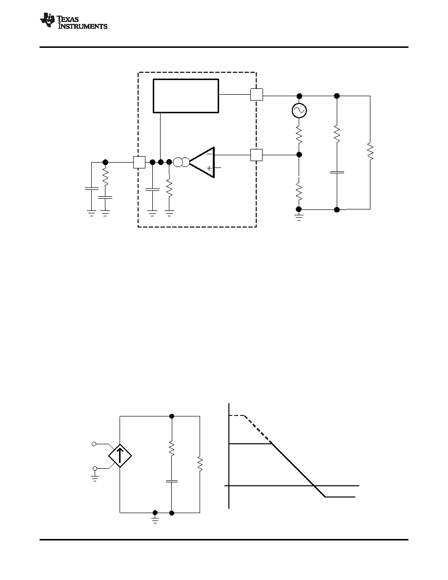
Figure 46. Small Signal Model for Loop Response
Simple Small Signal Model for Peak Current Mode Control
Figure 47 describes a simple small signal model that can be used to understand how to design the frequency
compensation. The TPS57040-Q1 power stage can be approximated to a voltage-controlled current source (duty
cycle modulator) supplying current to the output capacitor and load resistor. The control to output transfer
function is shown in Equation 14 and consists of a dc gain, one dominant pole, and one ESR zero. The quotient
of the change in switch current and the change in COMP pin voltage (node c in Figure 46) is the power stage
transconductance. The gmPS for the TPS57040-Q1 is 6A/V. The low-frequency gain of the power stage
frequency response is the product of the transconductance and the load resistance as shown in Equation 15.
As the load current increases and decreases, the low-frequency gain decreases and increases, respectively. This
variation with the load may seem problematic at first glance, but fortunately the dominant pole moves with the
load current (see Equation 16). The combined effect is highlighted by the dashed line in the right half of
Figure 47. As the load current decreases, the gain increases and the pole frequency lowers, keeping the 0-dB
crossover frequency the same for the varying load conditions which makes it easier to design the frequency
compensation. The type of output capacitor chosen determines whether the ESR zero has a profound effect on
the frequency compensation design. Using high ESR aluminum electrolytic capacitors may reduce the number
frequency compensation components needed to stabilize the overall loop because the phase margin increases
from the ESR zero at the lower frequencies (see Equation 17).
Figure 47. Simple Small Signal Model and Frequency Response for Peak Current Mode Control
Copyright
2010–2011, Texas Instruments Incorporated
27
相关PDF资料 |
PDF描述 |
|---|---|
| TPS57114QRTERQ1 | SWITCHING REGULATOR, 2000 kHz SWITCHING FREQ-MAX, PQCC16 |
| TPS60100PWP | 0.2 A SWITCHED CAPACITOR REGULATOR, 400 kHz SWITCHING FREQ-MAX, PDSO20 |
| TPS60101PWPG4 | SWITCHED CAPACITOR REGULATOR, 400 kHz SWITCHING FREQ-MAX, PDSO20 |
| TPS60101PWPRG4 | 0.1 A SWITCHED CAPACITOR REGULATOR, 400 kHz SWITCHING FREQ-MAX, PDSO20 |
| TPS60230RGTTG4 | 0.2 A SWITCHED CAPACITOR REGULATOR, 1250 kHz SWITCHING FREQ-MAX, PQCC16 |
相关代理商/技术参数 |
参数描述 |
|---|---|
| TPS57040QDRCRQ1 | 功能描述:直流/直流开关转换器 3.5-42Vin,0.5A Step Down SWIFT Cnvrtr RoHS:否 制造商:STMicroelectronics 最大输入电压:4.5 V 开关频率:1.5 MHz 输出电压:4.6 V 输出电流:250 mA 输出端数量:2 最大工作温度:+ 85 C 安装风格:SMD/SMT |
| TPS57060QDGQRQ1 | 功能描述:直流/直流开关转换器 3.5-60Vin,0.5A,2.5 MHz Step Down Cnvrtr RoHS:否 制造商:STMicroelectronics 最大输入电压:4.5 V 开关频率:1.5 MHz 输出电压:4.6 V 输出电流:250 mA 输出端数量:2 最大工作温度:+ 85 C 安装风格:SMD/SMT |
| TPS57060QDRCRQ1 | 功能描述:直流/直流开关转换器 3.5-60Vin,0.5A,2.5 MHz Step Down Cnvrtr RoHS:否 制造商:STMicroelectronics 最大输入电压:4.5 V 开关频率:1.5 MHz 输出电压:4.6 V 输出电流:250 mA 输出端数量:2 最大工作温度:+ 85 C 安装风格:SMD/SMT |
| TPS57112QRTERQ1 | 功能描述:直流/直流开关转换器 2.95-6Vin,2A,2MHz Sync St Down Cnvrtr RoHS:否 制造商:STMicroelectronics 最大输入电压:4.5 V 开关频率:1.5 MHz 输出电压:4.6 V 输出电流:250 mA 输出端数量:2 最大工作温度:+ 85 C 安装风格:SMD/SMT |
| TPS57114EVM | 制造商:Texas Instruments 功能描述:TPS57114EVM - Boxed Product (Development Kits) |
发布紧急采购,3分钟左右您将得到回复。