- 您现在的位置:买卖IC网 > PDF目录69517 > TPS62067DSGR (TEXAS INSTRUMENTS INC) 2 A SWITCHING REGULATOR, 3400 kHz SWITCHING FREQ-MAX, PDSO8 PDF资料下载
参数资料
| 型号: | TPS62067DSGR |
| 厂商: | TEXAS INSTRUMENTS INC |
| 元件分类: | 稳压器 |
| 英文描述: | 2 A SWITCHING REGULATOR, 3400 kHz SWITCHING FREQ-MAX, PDSO8 |
| 封装: | 2 X 2 MM, 0.75 MM HEIGHT, GREEN, PLASTIC, WSON-8 |
| 文件页数: | 7/28页 |
| 文件大小: | 1208K |
| 代理商: | TPS62067DSGR |
第1页第2页第3页第4页第5页第6页当前第7页第8页第9页第10页第11页第12页第13页第14页第15页第16页第17页第18页第19页第20页第21页第22页第23页第24页第25页第26页第27页第28页
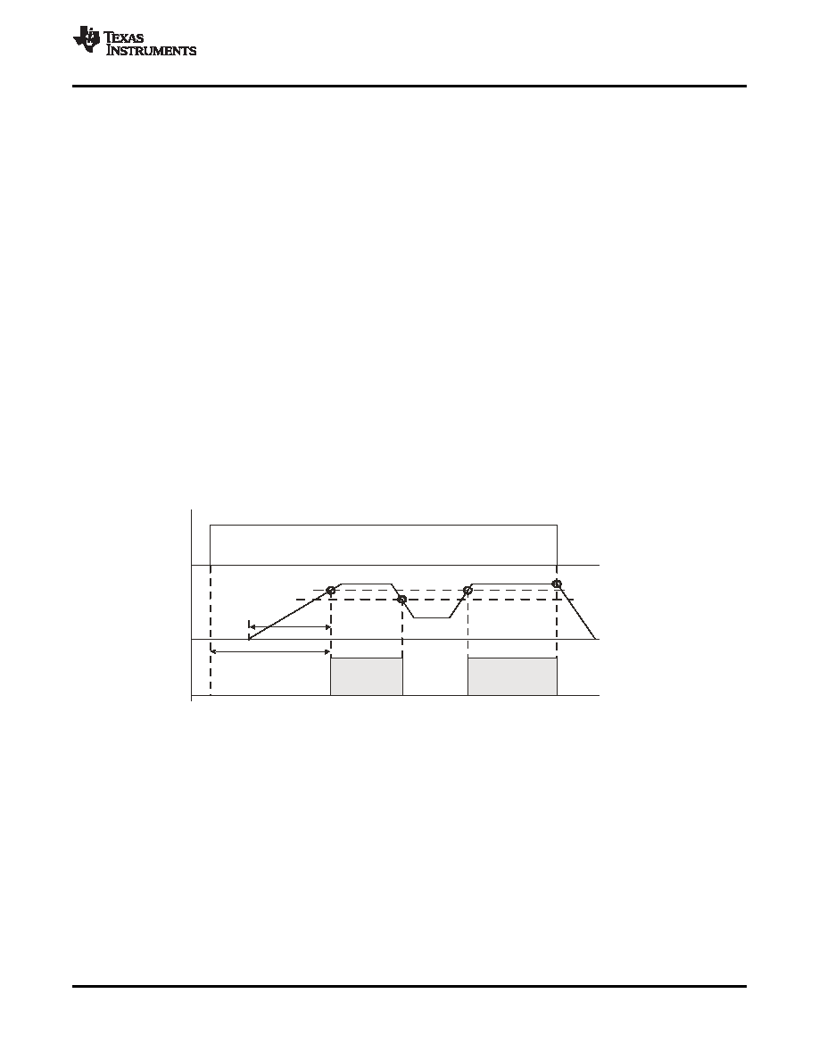
EN
VOUT
PG
95%
90%
Startup
Overload
Output
discharge
tStart
tRamp
WithEN=low
PG-->low
www.ti.com
SLVS833A – MARCH 2010 – REVISED MAY 2010
Connecting this pin to GND enables the Power Save Mode with automatic transition between PWM and PFM
mode. Pulling the MODE pin high forces the converter to operate in fixed frequency PWM mode even at light
load currents. This allows simple filtering of the switching frequency for noise sensitive applications. In this mode,
the efficiency is lower compared to the power save mode during light loads.
The condition of the MODE pin can be changed during operation and allows efficient power management by
adjusting the operation mode of the converter to the specific system requirements.
In device options where the MODE Pin is replaced with Power Good output, the Power Save Mode is enabled
per default.
POWER GOOD OUTPUT (TPS62067)
This function is available in the TPS62067. The Power Good Output is an open-drain output and requires an
external pull-up resistor. The circuit is active once the device is enabled and AVIN is above the undervoltage
lockout threshold VUVLO. It is driven by an internal comparator connected to the FB voltage. The PG output
provides a high level once the feedback voltage exceeds typically 95% of its nominal value. The PG output is
driven to low level once the feedback voltage falls below typically 90% of its nominal value. The PG output is
activated with an internal delay of 5s.
The PG open-drain output transistor is turned on immediately with EN = low level and pulls the output low. The
external pull up resistor can be connected to any voltage rail lower or equal the voltage applied to AVIN of the
device. The value of the pull-up resistor must be carefully selected in order to limit the current into the PG pin to
maximum 1.0mA. The external pull up resistor can be connected to VOUT or another voltage rail which does not
exceed the VIN level. The current flowing through the pull up resistor impacts the current consumption of the
application circuit in shutdown mode.
The shut down current of the device does not include the current through the external pull-up and internal
open-drain stage. The PG signal can be used for sequencing various converters or to reset a microcontroller.
Figure 25. Power Good Output PG
ENABLE
The device is enabled by setting EN pin to high. At first, the internal reference is activated and the internal
analog circuits are settled. Afterwards, the soft start is activated and the output voltage is ramped up. The output
voltages reaches 95% of its nominal value within tSTARTof typically 500 s after the device has been enabled. The
EN input can be used to control power sequencing in a system with various DC/DC converters. The EN pin can
be connected to the output of another converter, to drive the EN pin high and getting a sequencing of supply
rails. With EN = GND, the device enters shutdown mode. In this mode, all circuits are disabled and the SW pin is
connected to PGND via an internal resistor to discharge the output.
SOFT START
The TPS6206x has an internal soft start circuit that controls the ramp up of the output voltage. Once the
converter is enabled and the input voltage is above the undervoltage lockout threshold VUVLOthe output voltage
ramps up from 5% to 95% of its nominal value within tRamp of typ. 250s.
Copyright 2010, Texas Instruments Incorporated
15
相关PDF资料 |
PDF描述 |
|---|---|
| TPS62110MRSATEP | 2.4 A SWITCHING REGULATOR, 1100 kHz SWITCHING FREQ-MAX, PQCC16 |
| TPS62112MRSATEP | 2.4 A SWITCHING REGULATOR, 1100 kHz SWITCHING FREQ-MAX, PQCC16 |
| TPS62120DCN | SWITCHING REGULATOR, PDSO8 |
| TPS62122DRVT | SWITCHING REGULATOR, PDSO6 |
| TPS62201DBVTG4 | 0.67 A SWITCHING REGULATOR, 1500 kHz SWITCHING FREQ-MAX, PDSO5 |
相关代理商/技术参数 |
参数描述 |
|---|---|
| TPS62067DSGT | 功能描述:直流/直流开关转换器 3MHz 2A Step-Down Converter RoHS:否 制造商:STMicroelectronics 最大输入电压:4.5 V 开关频率:1.5 MHz 输出电压:4.6 V 输出电流:250 mA 输出端数量:2 最大工作温度:+ 85 C 安装风格:SMD/SMT |
| TPS62067DSGT | 制造商:Texas Instruments 功能描述:VOLTAGE REGULATOR IC 制造商:Texas Instruments 功能描述:IC, STEP-DOWN CONVERTER, WSON-8 |
| TPS62067QDSGRQ1 | 功能描述:Buck Switching Regulator IC Positive Adjustable 0.8V 1 Output 2A 8-WFDFN Exposed Pad 制造商:texas instruments 系列:汽车级,AEC-Q100 包装:剪切带(CT) 零件状态:在售 功能:降压 输出配置:正 拓扑:降压 输出类型:可调式 输出数:1 电压 - 输入(最小值):2.9V 电压 - 输入(最大值):6V 电压 - 输出(最小值/固定):0.8V 电压 - 输出(最大值):6V 电流 - 输出:2A 频率 - 开关:3MHz 同步整流器:是 工作温度:-40°C ~ 125°C (TJ) 安装类型:表面贴装 封装/外壳:8-WFDFN 裸露焊盘 供应商器件封装:8-WSON(2x2) 标准包装:1 |
| TPS62080ADSGR | 功能描述:直流/直流开关转换器 1.2A High Eff Step Down Converter RoHS:否 制造商:STMicroelectronics 最大输入电压:4.5 V 开关频率:1.5 MHz 输出电压:4.6 V 输出电流:250 mA 输出端数量:2 最大工作温度:+ 85 C 安装风格:SMD/SMT |
| TPS62080ADSGT | 功能描述:直流/直流开关转换器 1.2A High Eff Step Down Converter RoHS:否 制造商:STMicroelectronics 最大输入电压:4.5 V 开关频率:1.5 MHz 输出电压:4.6 V 输出电流:250 mA 输出端数量:2 最大工作温度:+ 85 C 安装风格:SMD/SMT |
发布紧急采购,3分钟左右您将得到回复。