- 您现在的位置:买卖IC网 > PDF目录98286 > TRC1300D (TEXAS INSTRUMENTS INC) RF, REMOTE CONTROL SUPPORT CIRCUIT, PDSO14 PDF资料下载
参数资料
| 型号: | TRC1300D |
| 厂商: | TEXAS INSTRUMENTS INC |
| 元件分类: | 摇控器 |
| 英文描述: | RF, REMOTE CONTROL SUPPORT CIRCUIT, PDSO14 |
| 封装: | PLASTIC, SO-14 |
| 文件页数: | 22/27页 |
| 文件大小: | 358K |
| 代理商: | TRC1300D |
第1页第2页第3页第4页第5页第6页第7页第8页第9页第10页第11页第12页第13页第14页第15页第16页第17页第18页第19页第20页第21页当前第22页第23页第24页第25页第26页第27页
TRC1300, TRC1315
MARCSTAR
I E/D
REMOTE CONTROL ENCODER/DECODERS
SLWS011D – AUGUST 1996 – REVISED JANUARY 1997
4
POST OFFICE BOX 655303
DALLAS, TEXAS 75265
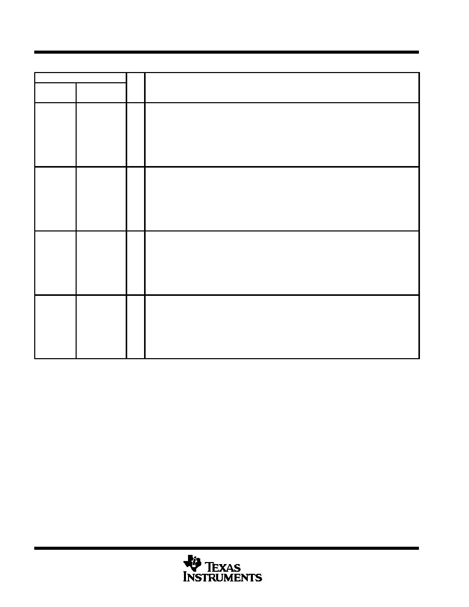
Terminal Functions
TERMINAL
NAME
NO.
I/O
DESCRIPTION
NAME
D
N
VRC/TX1
8
9
I/O
Function 1 VRC (valid received code) output and function 1 encode enable. In the decode mode,
VRC/TX1 is an output that goes to a logic-low state (for one frame — 768 clocks) when the device
receives the correct 40 bits of security code and function data (4 bits) matching function 1. In the
encoder mode, VRC/TX1 is an input that initiates the encoding of function 1 and output of function 1
data. When VRC/TX1 is pulled to GND, the device continuously outputs the function-1 code sequence
stored in EEPROM memory from DIN/DOUT up to 360 times. The device cannot transmit function-1
code again until VRC/TX1 is again pulled to GND. VRC/TX1 has an internal pullup resistor in both the
encoder and decoder modes, and switch debouncing in the encoder mode.
VRC/TX2
9
10
I/O
Function 2 VRC (valid received code) output and function 2 encode enable. In the decode mode,
VRC/TX2 is an output that goes to a logic-low state (for one frame — 768 clocks) when the device
receives the correct 40 bits of security code and function data (4 bits) matching function 2. In the
encoder mode, VRC/TX2 is an input that initiates the encoding of function 2 and output of function 2
data. When VRC/TX2 is pulled to GND, the device continuously outputs the function-2 code sequence
stored in EEPROM memory from DIN/DOUT up to 360 times. The device cannot transmit function-2
code again until VRC/TX2 is again pulled to GND. VRC/TX2 has an internal pullup resistor in both the
encoder and decoder modes, and switch debouncing in the encoder mode.
VRC/TX3
10
12
I/O
Function 3 VRC (valid received code) output and function 3 encode enable. In the decode mode,
VRC/TX3 is an output that goes to a logic-low state (for one frame — 768 clocks) when the device
receives the correct 40 bits of security code and function data (4 bits) matching function 3. In the
encoder mode, VRC/TX3 is an input that initiates the encoding of function 3 and output of function 3
data. When VRC/TX3 is pulled to GND, the device continuously outputs the function-3 code sequence
stored in EEPROM memory from DIN/DOUT up to 360 times. The device cannot transmit function-3
code again until VRC/TX3 is again pulled to GND. VRC/TX3 has an internal pullup resistor in both the
encoder and decoder modes, and switch debouncing in the encoder mode.
VRC/TX4
11
13
I/O
Function 4 VRC (valid received code) output and function 4 encode enable. In the decode mode,
VRC/TX4 is an output that goes to a logic-low state (for one frame — 768 clocks) when the device
receives the correct 40 bits of security code and function data (4 bits) matching function 4. In the
encoder mode, VRC/TX4 is an input that initiates the encoding of function 4 and output of function 4
data. When VRC/TX4 is pulled to GND, the device continuously outputs the function-4 code sequence
stored in EEPROM memory from DIN/DOUT up to 360 times. The device cannot transmit function-4
code again until VRC/TX4 is again pulled to GND. VRC/TX4 has an internal pullup resistor in both the
encoder and decoder modes, and switch debouncing in the encoder mode.
absolute maximum ratings over operating free-air temperature range (unless otherwise noted)
Supply voltage range, TRC1300, VCC (see Note 1)
– 0.6 V to 7 V
. . . . . . . . . . . . . . . . . . . . . . . . . . . . . . . . . . . .
TRC1315, VCC (see Note 1)
– 0.6 V to 15 V
. . . . . . . . . . . . . . . . . . . . . . . . . . . . . . . . . . .
Input voltage, logic/analog signals, VI
– 0.6 V to 7 V
. . . . . . . . . . . . . . . . . . . . . . . . . . . . . . . . . . . . . . . . . . . . . . . . .
Operating free-air temperature range, TA
–40
°C to 85°C
. . . . . . . . . . . . . . . . . . . . . . . . . . . . . . . . . . . . . . . . . . . .
Storage temperature range
– 65
°C to 150°C
. . . . . . . . . . . . . . . . . . . . . . . . . . . . . . . . . . . . . . . . . . . . . . . . . . . . . . . .
ESD protection, all terminals, human body
2 kV
. . . . . . . . . . . . . . . . . . . . . . . . . . . . . . . . . . . . . . . . . . . . . . . . . . . .
machine
200 V
. . . . . . . . . . . . . . . . . . . . . . . . . . . . . . . . . . . . . . . . . . . . . . . . . . . . . . .
JEDEC latchup
120 mA or 13.2 V
. . . . . . . . . . . . . . . . . . . . . . . . . . . . . . . . . . . . . . . . . . . . . . . . . . . . . . . . . . . . . . . .
Stresses beyond those listed under “absolute maximum ratings” may cause permanent damage to the device. These are stress ratings only, and
functional operation of the device at these or any other conditions beyond those indicated under “recommended operating conditions” is not
implied. Exposure to absolute-maximum-rated conditions for extended periods may affect device reliability.
NOTE 1: Voltage values are with respect to GND.
相关PDF资料 |
PDF描述 |
|---|---|
| TRC1315N | RF, REMOTE CONTROL SUPPORT CIRCUIT, PDIP16 |
| TRC1315DR | RF, REMOTE CONTROL SUPPORT CIRCUIT, PDSO14 |
| TRC1315D | RF, REMOTE CONTROL SUPPORT CIRCUIT, PDSO14 |
| TRF7960RHBR | SPECIALTY CONSUMER CIRCUIT, PQCC32 |
| TRF7960RHBT | SPECIALTY CONSUMER CIRCUIT, PQCC32 |
相关代理商/技术参数 |
参数描述 |
|---|---|
| TRC1300N | 制造商:Rochester Electronics LLC 功能描述:- Bulk |
| TRC1315 | 制造商:TI 制造商全称:Texas Instruments 功能描述:MARCSTAR I E/D REMOTE CONTROL ENCODER/DECODERS |
| TRC1315D | 制造商:Rochester Electronics LLC 功能描述:- Bulk |
| TRC1315N | 制造商:Rochester Electronics LLC 功能描述:- Bulk |
| TRC1331S-501 | 功能描述:LED TRIPLE 1.1W COOL WHITE 30DEG RoHS:是 类别:光电元件 >> LED - 高亮度电源模块 系列:1W-型 标准包装:36 系列:5027 TFFC STAR K2 颜色:暖白色 配置:星形 在特定电流下的光通量 - 测试:75lm 电流 - 测试:350mA 电流 - 最大:1.5A 带连接器:无 驱动器电路:无 波长:- 电压:- |
发布紧急采购,3分钟左右您将得到回复。